Tx 5.3.3 common mode spectrum (cjtpat), Figure 16 - common mode rms voltage results, Qphy-sas3 software option – Teledyne LeCroy QPHY-SAS3 User Manual
Page 25
QPHY-SAS3 Software Option
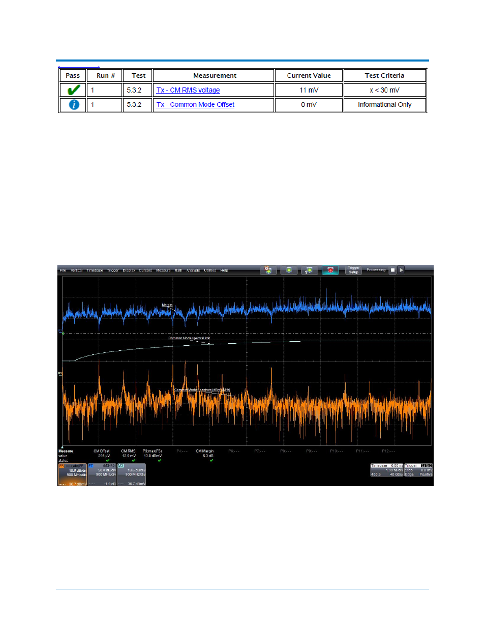
Figure 16 - Common Mode RMS Voltage Results
In the Measure section:
• CM Offset (P1) is the common mode offset. This is measured by taking the mean of the common
mode trace. This is the measured value of Tx – Common Mode Offset (5.3.2). This test is
informational only.
• CM RMS (P2) is the common mode RMS voltage. This is measured by taking the RMS of the
common mode trace. This is the measured value for Tx – CM RMS voltage (5.3.2). This value
must be less than 30mV in order to pass this test.
Tx 5.3.3 Common Mode Spectrum (CJTPAT)
The purpose of this test is to verify that the common-mode spectrum is within the specification limits. After
the completion of the Common Mode RMS Voltage test the oscilloscope is in the following configuration:
Figure 17 - Oscilloscope Configuration after the Common Mode Spectrum Test
Shown on this screen:
• F5 is the Common Mode Spectrum trace. This is the FFT of the common mode trace displayed in
dBmV/MHz. The common mode trace is calculated by summing the differential inputs and
dividing by 2.
922545 Rev A
25