Tx 5.3.2 common mode rms voltage (cjtpat), Figure 14 - phy link rate stability test results – Teledyne LeCroy QPHY-SAS3 User Manual
Page 24
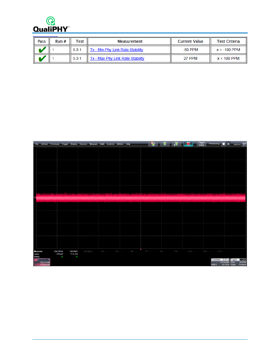
Figure 14 - Phy Link Rate Stability Test Results
In the Measure section:
• P1 and P2 are used to calculate the min and the max of F2. These are the measured values for Tx
– Min Phy Link Rate Stability (5.3.1) and Tx – Max Phy Link Rate Stability (5.3.1). These
values must be between +/- 100ppm in order to pass this test.
Tx 5.3.2 Common Mode RMS Voltage (CJTPAT)
The purpose of this test is to verify that the common-mode RMS voltage is within the specification limits.
After the completion of the Common Mode RMS Voltage test the oscilloscope is in the following
configuration:
Figure 15 - Oscilloscope Configuration after the Common Mode RMS Voltage Test
Shown on this screen
• F2 is the Common Mode Trace. This is calculated by summing the two inputs and dividing by 2.
24
922545 Rev A
- WaveAce EasyScope Operators Manual (28 pages)
- PeRT3 Software Interface (15 pages)
- FireInspector Automation Application Programming Interface (92 pages)
- PETracer ProtoSync Software User Manual (154 pages)
- QPHY-PCIe3-Tx-Rx (32 pages)
- Signal Integrity Studio (14 pages)
- Serial Data Debug Solutions (204 pages)
- Line Code and Symbolic Decoders (20 pages)
- AORM - Advanced Optical Recording Measurements (125 pages)
- CANbus TD - Quick Reference Guide (8 pages)
- CANbus TD and CANbus TDM - Operators Manual (69 pages)
- FlexRay Trigger, Decode and Physical Layer Test (32 pages)
- MIPI D-PHY (15 pages)
- DFP2 - Digital Filter Package 2 (22 pages)
- ET-PMT - Electrical Telecom Pulse Mask Testing (11 pages)
- ENETbusD Decoder (16 pages)
- Eye Doctor II (45 pages)
- JitKit (16 pages)
- JTA2 (31 pages)
- Power Analyzer Package (34 pages)
- QPHY-10GBase-KR (28 pages)
- QPHY-10GBase-T (36 pages)
- QPHY-BroadR-Reach (33 pages)
- QPHY-DDR2 (47 pages)
- QPHY-DDR3 (44 pages)
- QPHY-DDR4 (73 pages)
- QPHY-DisplayPort (19 pages)
- QPHY-ENET (78 pages)
- QPHY-HDMI (37 pages)
- QPHY-LPDDR2 (49 pages)
- QPHY-MIPI-DPHY (32 pages)
- QPHY-MOST150 (24 pages)
- QPHY-MOST50 (21 pages)
- QPHY-PCIe (30 pages)
- QPHY-PCIE3 (28 pages)
- QPHY-SAS2 (45 pages)
- QPHY-SATA (45 pages)
- QPHY-USB (66 pages)
- QPHY-USB3-Tx-Rx (47 pages)
- QPHY-UWB (30 pages)
- SDA II (38 pages)
- SDA III-CompleteLinQ (59 pages)
- Spectrum Analyzer (14 pages)
- USB2 Decoder (24 pages)