1 introduction, Ntroduction – Teledyne LeCroy PCI Express 2.0 Mid-Bus Probe Ver.2.40 User Manual
Page 5
Teledyne LeCroy
PCIe 2.0 Mid-Bus Probe Installation Guide
Version 2.4
1
1 Introduction
Teledyne LeCroy offers a wide variety of ways to connect PCI Express protocol analyzers to products
under test. There are four common methods: Interposers, Specialty Probes, Mid-Bus Probes and Multi-
lead Probes.
If the product uses a standard PCI Express card connector, an interposer is used which is inserted
between the PCIe Card and the card slot. The interposer taps off the data traffic to allow the analyzer to
monitor and record traffic with minimal perturbation of the electrical interface.
Specialty probes are used with specific card configurations, and are used in the same manner as an
interposer card (in fact a specialty probe is an interposer card designed for a specific interface). Teledyne
LeCroy supports a range of specialty probes including ExpressCard, AMC, XMC, ExpressModule, and HP
Blade Server interfaces.
If the product has an embedded PCI Express bus (e.g., a bus which runs between chips on the same
circuit board), then either a mid-bus probe or a multi-lead probe can be used. The mid-bus probe
requires a connection footprint (see below) to be designed into the board. The multi-lead probe allows
individual connections to each bus trace on the board.
The Teledyne LeCroy mid-bus probes are 16-channel differential signal probes that meet the demand for
high-density signal access, accuracy and repeatability while providing connector-less attachment to the
device under test. They are based upon the configuration that was initially recommended in the Intel PCI
Express Mid-Bus Probing Footprint and Pinout Revision 1.0 document dated 8/05/03 and the subsequent
revisions.
A mid-bus probe is one of the tools that can greatly help engineers debugging PCI Express buses. A PCI
Express mid-bus probing solution provides direct probing capability of a PCI Express bus at a width of up
to 16 lanes. To accommodate a mid-bus probe, a special pad layout is required to expose the PCI
Express differential pairs on the surface of the target board.
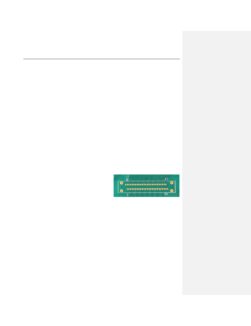
Although not part of the PCI Express specifications, the
industry has developed a common mid-bus probe footprint
for Gen1 and Gen2 applications as shown on the right.
This footprint is recommended for use with all types of test
equipment including protocol analyzers, logic analyzers
and oscilloscopes. The required pad layout can be in x4
(half-size), x8 (full-size) or x16 (dual full-size) configurations depending on the maximum number of lanes
that need to be probed. All footprint sizes support probing at reduced lane widths (e.g., x1) and lane
widths up to the maximum footprint size. In the photo shown on page 3, the footprint occurs on the target
board at "B". Note that this manual documents the mid-bus footprint used for Gen1 and Gen2
applications; the probe footprint for Gen3 is covered in the PCI Express 3.0 Mid-Bus Probe User Manual.
Teledyne LeCroy makes three versions of mid-bus probes, one for Gen 1 (2.5 GT/s data rates), one for
Gen2 (2.5 and 5 GT/s data rates) and one for Gen3 (2.5, 5 and 8 GT/s data rates). The Gen3 mid-bus
probe is for use with the Summit T3-16 or T3-8 Analyzers, and is documented in the PCI Express 3.0 Mid-
Bus Probe User Manual.
The Gen2 mid-bus probe is intended for use with the Summit T28 or Summit T2-16 Analyzers (PCIe 2.0),
and the Gen1 mid-bus probe for use with the PETracer ML and PETracer EML analyzers. The Summit
Analyzers also support the Gen1 mid-bus probe, and the Summit T3-16 and T3-8 support the Gen2 mid-
bus probe. Each probe is available in two versions: a full-size probe and a half-size probe. The full-size
probe for the PETracer ML is shown on page 3. It has a two-strand ribbon cable (D) and a x16 connection
header (B). A half-size probe has a single strand ribbon cable and a x8 connection header.