4 pin assignments for x8 lane widths, Pin assignments for x8 lane widths – Teledyne LeCroy PCI Express 2.0 Mid-Bus Probe Ver.2.40 User Manual
Page 18
Teledyne LeCroy
PCIe 2.0 Mid-Bus Probe Installation Guide
Version 2.4
14
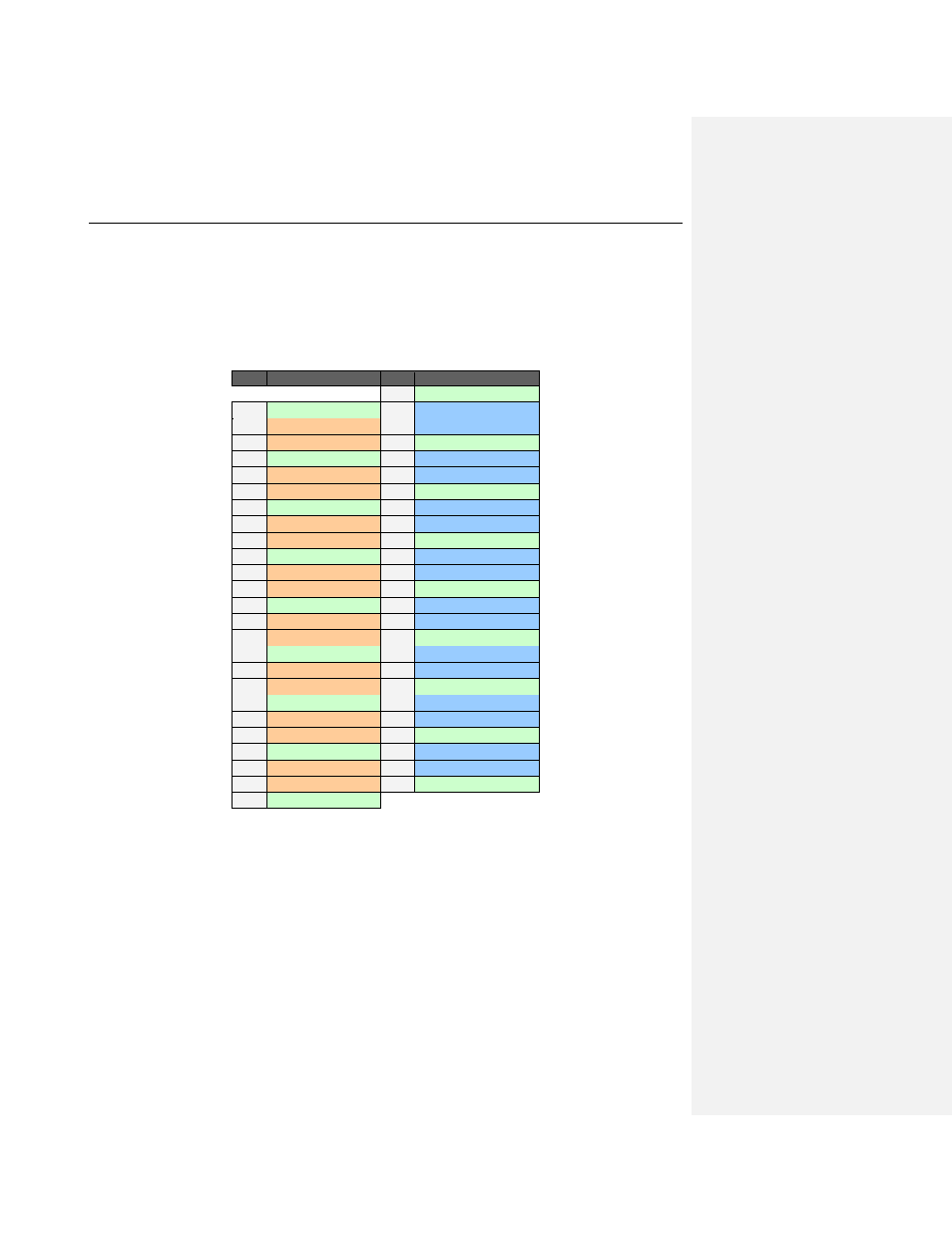
4.4 Pin Assignments for x8 Lane Widths
For x8 lane widths, one full-size header is required. The diagram below shows the recommended pin
assignments for x8 configurations (keep in mind that any of modifications mentioned in Section 4.2 can
be applied, and in addition the lane swizzling feature of the Summit T3-16 and T2-16 systems noted in
Section 4.2).
x8 (Bi-directional) Mid-Bus Probe Pinout
on a Full-size Header
Pin
Signal Name
Pin
Signal Name
G1
GND (Gen2 only)
2
GND
1
C0p- Upstream
4
C0p- Downstream
3
C0n- Upstream
6
C0n- Downstream
5
GND
8
GND
7
C1p- Upstream
10
C1p- Downstream
9
C1n- Upstream
12
C1n- Downstream
11
GND
14
GND
13
C2p- Upstream
16
C2p- Downstream
15
C2n- Upstream
18
C2n- Downstream
17
GND
20
GND
19
C3p- Upstream
22
C3p- Downstream
21
C3n- Upstream
24
C3n- Downstream
23
GND
26
GND
25
C4p- Upstream
28
C4p- Downstream
27
C4n- Upstream
30
C4n- Downstream
29
GND
32
GND
31
C5p- Upstream
34
C5p- Downstream
33
C5n- Upstream
36
C5n- Downstream
35
GND
38
GND
37
C6p- Upstream
40
C6p- Downstream
39
C6n- Upstream
42
C6n- Downstream
41
GND
44
GND
43
C7p- Upstream
46
C7p- Downstream
45
C7n- Upstream
48
C7n- Downstream
47
GND
G2
GND (Gen2 only)