6 daisy chain cable (for x16 applications), Daisy chain cable (for x16 applications) – Teledyne LeCroy PCI Express 2.0 Mid-Bus Probe Ver.2.40 User Manual
Page 14
Teledyne LeCroy
PCIe 2.0 Mid-Bus Probe Installation Guide
Version 2.4
10
The reference clock is captured separately with a dedicated probe cable. Considering the possibility that
one clock may be shared between two physically separated mid-bus probes, each mid-bus probe pod is
equipped with a reference clock output port. The reference clock probe can capture signals from the
target system or receive a duplicated reference clock from another mid-bus probe board.
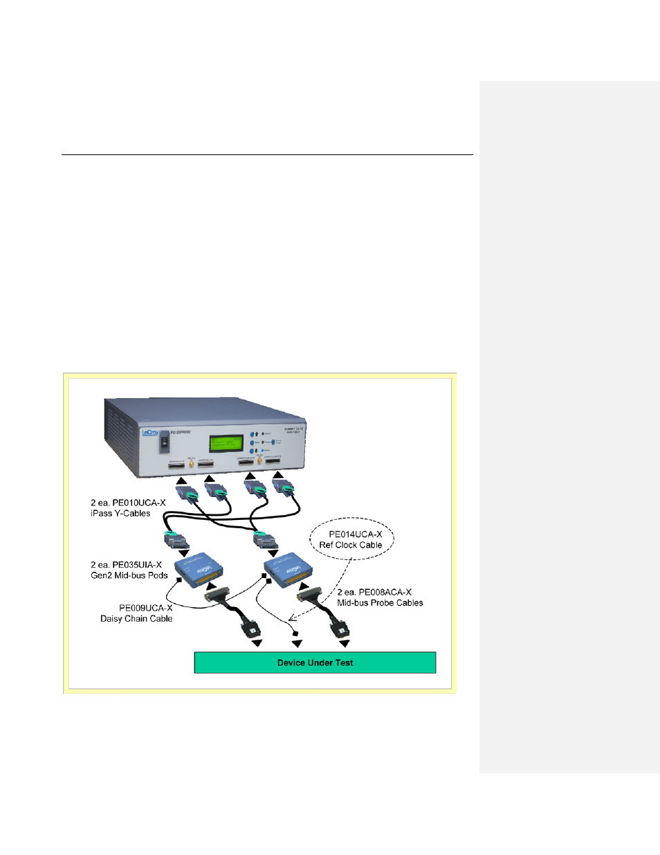
3.6 Daisy Chain Cable (for x16 applications)
A single mid-bus probe pod can capture traffic on bus widths up to x8. If x16 lane widths are required
(e.g., when using a Summit T2-16 Analyzer with a x16 device), two Mid-Bus Probe Pods are required.
In this configuration, one of the pods is connected to the DUT to tap the Reference Clock signal, and the
second pod is “daisy-chained” to the first pod using the PE009UCA-X Daisy Chain Cable. Connect the
Ref Clock cable to the CLK IN port of the first pod, and connect the Daisy Chain Cable between the CLK
OUT port of the first pod and the CLK IN port of the second pod.
Mid-bus Probe Setup for x16 lane widths (using Summit T2-16 Analyzer)