6 pin assignments for x2 lane widths, Pin assignments for x2 lane widths – Teledyne LeCroy PCI Express 2.0 Mid-Bus Probe Ver.2.40 User Manual
Page 20
Teledyne LeCroy
PCIe 2.0 Mid-Bus Probe Installation Guide
Version 2.4
16
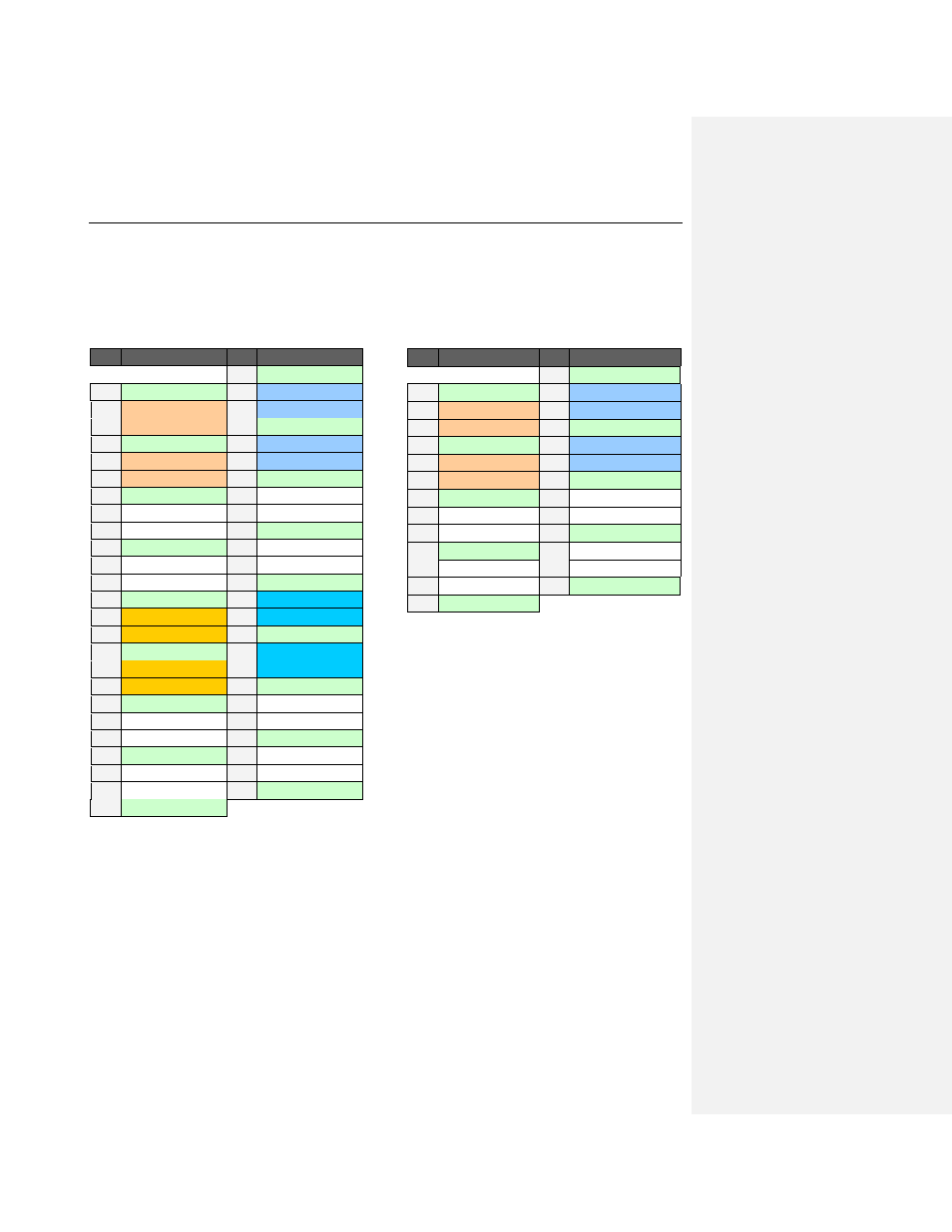
4.6 Pin Assignments for x2 Lane Widths
For x2 lane widths, either a full-size header or a half-size header can be used. The diagram below shows
the recommended pin assignments for x2 configurations).
Dual x2 (Bi-directional) Mid-Bus Probe
Pinout on a Full-size Header
Pin
Signal Name
Pin
Signal Name
G1
GND (Gen2 only)
2
GND
1
C0p- Upstream1
4
C0p- Downstream1
3
C0n- Upstream1
6
C0n- Downstream1
5
GND
8
GND
7
C1p- Upstream1
10 C1p- Downstream1
9
C1n- Upstream1
12 C1n- Downstream1 11
GND
14
GND
13
nc
16
nc
15
nc
18
nc
17
GND
20
GND
19
nc
22
nc
21
nc
24
nc
23
GND
26
GND
25
C0p- Upstream2*
28 C0p- Downstream2* 27
C0n- Upstream2*
30 C0n- Downstream2* 29
GND
32
GND
31
C1p- Upstream2*
34 C1p- Downstream2* 33
C1n- Upstream2*
36 C1n- Downstream2* 35
GND
38
GND
37
nc
40
nc
39
nc
42
nc
41
GND
44
GND
43
nc
46
nc
45
nc
48
nc
47
GND
G2
GND (Gen2 only)
Note that in a full-size header there is room for up to
four x2 PCIe bus connections (pins 1-12, 13-24, 25-
36, and 37-48).
If using a PETracer analyzer, the analyzer will always
look for the x2 link in the top set of pins (pins 1-12),
although by physically reversing the header connector
you can also connect to the lowest set (pins 37-48).
If using a Summit T2-16 Analyzer, you can use the
lane swizzling feature to define any connection
pattern and connect to any of the four locations.
With either analyzer, although connection to more
than one bus is possible, traffic is recorded from only
one designated bus at any given time
.
x2 (Bi-directional) Mid-Bus Probe Pinout
on a Half-size Header
Pin
Signal Name
Pin
Signal Name
G1
GND (Gen2 only)
2
GND
1
C0p- Upstream
4
C0p- Downstream
3
C0n- Upstream
6
C0n- Downstream
5
GND
8
GND
7
C1p- Upstream
10
C1p- Downstream
9
C1n- Upstream
12
C1n- Downstream 11
GND
14
GND
13
nc
16
nc
15
nc
18
nc
17
GND
20
GND
19
nc
22
nc
21
nc
24
nc
23
GND
G2
GND (Gen2 only)
Note that in a half-size header there is room for up to
two x2 PCIe bus connections (pins 1-12 and 13-24).
If using a PETracer analyzer, the analyzer will always
look for the x2 link in the top set of pins (pins 1-12),
although by physically reversing the header connector
you can also connect to the lowest set (pins 13-24).
If using a Summit T2-16 Analyzer, you can use the
lane swizzling feature to define any connection
pattern and therefore connect to any of the four
possible locations.
With either analyzer, although connection to more
than one bus is possible, traffic is recorded from only
one designated bus at any given time
.