Teledyne LeCroy PCI Express 2.0 Mid-Bus Probe Ver.2.40 User Manual
Page 23
Teledyne LeCroy
PCIe 2.0 Mid-Bus Probe Installation Guide
Version 2.4
19
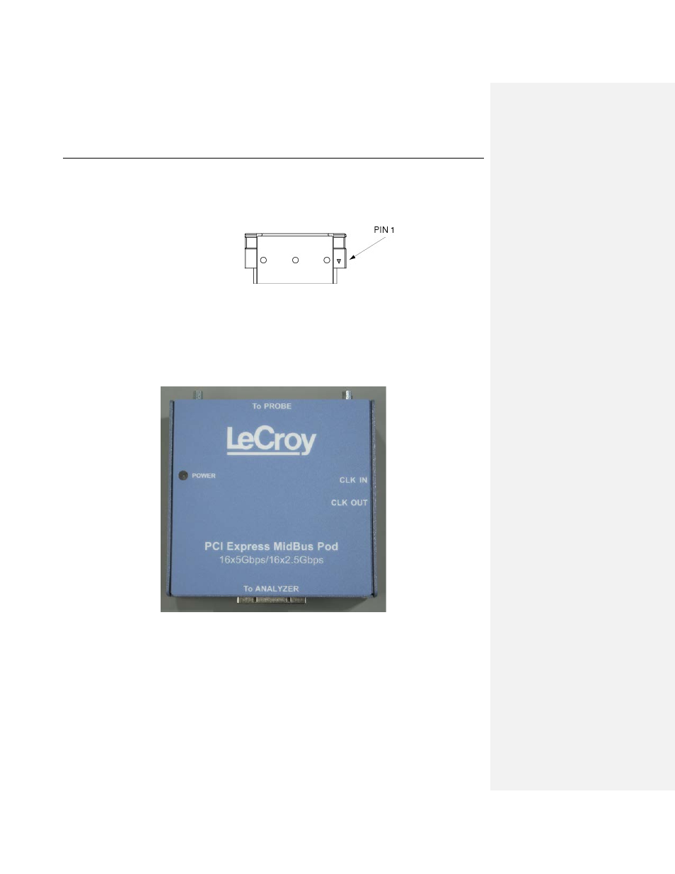
Note:
The probe design is not keyed, to allow probing of different mid-bus signal
assignments. A small triangle on the side of the probe header housing (shown
below) indicates the position of pin 1 of the mid-bus footprint (as indicated in the
Mid-Bus Probe Footprint specifications). Incorrect orientation of the probe header
results in bad recording.
4.
Carefully tighten the probe to the target by using the two thumbscrews. The thumbscrews
should be screwed in only finger-tight.
Caution: The probe is delicate equipment. Please tighten the thumbscrew carefully while
watching the LEDs on the probe pod. Over-tightening the probe header might
damage the miniature probing spring pins.
5.
Connect the other side of the probe cable to the mid-bus probe pod port marked “To Probe”.
The mid-bus probe pod amplifies the signal and sends it to the analyzer. The PCIe 2.0
(Gen2) probe pod is shown below.
6.
If you intend to use the analyzer's reference clock, connect the three pin clock cable to the
port marked "Ref Clock In" (Reference Clock In) on the mid-bus probe pod.
7.
Connect the other end of the clock cable to the three-pin reference clock header on the PCI
Express board. Orientation of the cable does not matter.
8.
Connect the analyzer cable to the pod port marked “To Analyzer.”
9.
Connect the other side of the cable to the analyzer as described in the following section.