2 mid-bus probe retention, Mid-bus probe retention – Teledyne LeCroy PCI Express 2.0 Mid-Bus Probe Ver.2.40 User Manual
Page 12
Teledyne LeCroy
PCIe 2.0 Mid-Bus Probe Installation Guide
Version 2.4
8
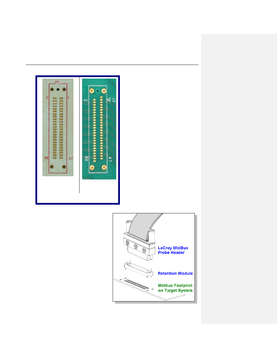
A typical layout of a mid-bus footprint might look something like the following two pictures:
Gen1 Mid-Bus Layout Gen2 Mid-Bus Layout
P C B l a y o u t
3.2 Mid-bus Probe Retention
To prepare a circuit board for PCI Express mid-bus
probing, the mid-bus footprint has to be laid out
onto the target system board and a retention
module has to be attached to the board. Retention
module attachment is simple and quick. There are
four through-hole pins and one protrusion key
underneath the retention module. Align the key of
the retention module with the keying/alignment
hole in the mid-bus footprint on the target system
board, and solder the through-hole pins to the
matching plated through holes located on each
corner of the mid-bus footprint. The mid-bus probe
can then be attached to the target system board
through the retention module to provide
mechanical support for pin-to-pin alignment. The
mid-bus probe has 2 retention screws that connect
to the retention module to hold the probe in place.