3 probe connection to analyzer, 4 probe keepout volume, 5 reference clock probe attachment – Teledyne LeCroy PCI Express 2.0 Mid-Bus Probe Ver.2.40 User Manual
Page 13: Probe connection to analyzer, Probe keepout volume, Reference clock probe attachment
Teledyne LeCroy
PCIe 2.0 Mid-Bus Probe Installation Guide
Version 2.4
9
The retention module should not be confused with a PCB connector because it is not part of the electrical
circuits of either the target system or the probe. With the use of a retention module, the requirement to
have a keep out area on the backside of the board is eliminated.
Retention modules can be purchased through Teledyne LeCroy:
• Full-size: P/N 232-0003-00
• Half-size: P/N 232-0004-00
3.3 Probe Connection to Analyzer
The bus signals captured by the mid-bus probe are connected to a mid-bus probe pod for amplification.
This reduces the load imposed by the mid-bus probe on the target system, while allowing a longer cable
to attach to the Teledyne LeCroy PCI Express protocol analyzer. The Teledyne LeCroy PCI Express
protocol analyzer can then interpret these signals for full decoding and protocol analysis.
3.4 Probe Keepout Volume
As with any connection to a PCB, sufficient clearance must be allowed around the point where the probe
will connect. This is defined as the keep-out volume, which must be kept clear of other components
mounted on the PCB.
The probe keepout volumes are shown in the diagrams in Section 3.1.
3.5 Reference Clock Probe Attachment
Should SSC clocking be used in the system under test or if the link varies the bit rate by more than
300ppm, a reference clock tap may be required. The connection from the reference clock to the analyzer
is a 3-pin header (1 by 3, 0.050” center spacing) which is placed on the clock signal transmission line of
the DUT. The PE014UCA-X Reference Clock Cable provides a three-pin micro socket that connects from
this header to the CLK IN port on the Mid-Bus Pod.
If the reference clock is sampled by tapping off an existing clock, the header shall be located on the
existing clock transmission line, where a high impedance clock probe from the mid-bus probe is
connected with no significant loading effects. In the case of a dedicated clock, the header shall be
located at the end of a dedicated clock transmission line without termination, where a 50-Ohm cable is
connected and the termination for the clock signal is provided on the mid-bus probe board.
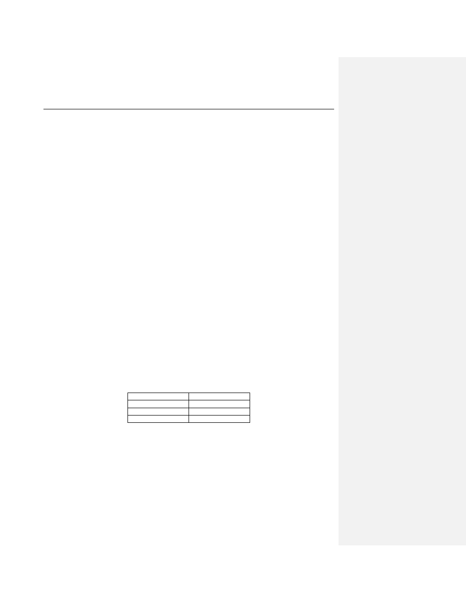
The connectivity of the clock header pins follows the following table:
Signal
Pin Number
REFCLKp
1 (or 3)
Unused
2
REFCLKn
3 (or 1)
Note that the analyzer is not sensitive to the polarity of the reference clock. Therefore, the probe can be
plugged onto the pin header in either orientation.
The following 3-pin header can be used for the reference clock:
Samtec Part No: TMS-103 (Vertical Orientation)