Important, Assembly instructions, Operation – Foredom PowerGraver User Manual
Page 4: Connecting motor and control, Connecting the handpiece, Installing accessories, Changing collets, Adjusting impact of hammer, Stroke/speed adjustment
Assembly Instructions
Always make sure your power tool is
unplugged during assembly.
The PowerGraver ships with the shaft and
sheath assembled, however,
please check to
be sure that the tip of the shaft extends
3⁄4
″ beyond the end of the sheath. If it
needs to be
adjusted, place the
entire unit on a flat
surface with shaft
and sheath
extended straight.
Adjust the
exposed tip of the flexible shaft so that it
extends 3/4
″ beyond the sheath, as shown.
This is done by loosening the set screw in the
motor connector and moving the sheath in or
out of the motor connector. When the correct
adjustment is made, tighten the set screw in
the connector. See photo on bottom of page 6.
Connecting the Handpiece:
Unlike other Foredom Handpieces, the H.9D
handpiece has a tab on the end where it con-
nects to the shaft and sheath (see drawing).
The tab slides over the flattened edge on the
sheath. The H.9D will not fit other Foredom
sheaths. However, other handpieces can
be attached to the PowerGraver shaft for
slow speed jobs.
The Foredom PowerGraver Kit K.2293 also
includes collet changing wrenches, handpiece
oil, flexible shaft grease, 32-minute instructional
DVD and booklet.
flattened edge of sheath
tab
Operation
Read all safety instructions on pages 2 and 3
before using your Foredom PowerGraver.
Wear proper eye and face protection to pro-
tect yourself from injuries caused by flying
debris or chips from the work being done.
Your Foredom motor may be operated in a ver-
tical or horizontal position. If the motor is hung
up above a workbench, be sure to
fasten it securely.
Do Not Bend the Flexible Shaft at a Tight
Angle. Shafts and sheaths last longer when
they are used without sharp bends. If used at
angles or loops, wear will occur at the points of
greatest friction.
4
IMPORTANT!
1. In addition to aligning the outer tab, the
keyed tip at the end of the flexible shaft must be
lined up with the keyway inside the end of the
handpiece. Do this by looking into the rear of
the handpiece before pushing it on. If it is not in
line, turn the key tip or the handpiece to the
correct position while being sure to also align
the outer tab with the flat outer edge of the
shaft. Both connections must be properly
aligned and they move or turn independently
of eachother. The handpiece is easy to remove
from the flexible shaft. To remove, simply pull
the handpiece off the shaft and sheath with a
firm grip.
2. Install the Palm Rest. Slide the larger
opening over the front of the handpiece and
place it as close to the impact adjustment ring
as possible. Rotate the palm rest to the most
comfortable position and tighten set screw with
a small flat-head screwdriver. Use of the palm
rest is a matter of personal preference. You may
find that the palm rest is more appropriate for
some applications than others.
Installing Accessories
The PowerGraver can take standard gravers and
other accessories with 1/16
″ (1.6mm), 3/32″
(2.35mm), 1/8
″ (3.18mm) and 3mm diameter
shanks. Choose the correct accessory for your
particular application. We recommend that you
grind and trim standard graver shanks to the
dimension illustrated above.
Locate and identify all components before
discarding the packing list and materials that
came with your PowerGraver.
An optional on/off foot switch is available.
To install an accessory, insert one wrench into
the wrench flats of handpiece. Insert other
wrench into wrench flats of chuck nut. Loosen
chuck nut. Insert accessory as far as possible
into the collet. Tighten chuck nut. Test for a
secure hold by pulling on accessory. Remove
wrenches. To release an accessory, follow the
same steps.
Changing Collets
The H.9D handpiece has collets to fit four
different shank sizes: 1/16
″, 3/32″, 1/8″ and
3mm. To use the correct collet size for the
shank of the accessory you are using, it is
sometimes necessary to change a collet. The
1
″
1
⁄
8
″
Grind corners of shank
to dimension shown for
snug fit into collet.
collet holds the accessory securely in the
handpiece. Unscrew the chuck nut and slip out
collet. Slip in new collet and screw the chuck
nut back into place.
Adjusting Impact of Hammer
The impact of the stroke is adjusted by rotating
the knurled ring on the handpiece clockwise
towards the chuck nut for a lighter impact –
and counterclockwise towards the back for a
heavier impact.
Chuck Nut
Impact
Adjustment Ring
Palm Rest
Do Not Force the Tool. Let the speed of
the tool do the work. Avoid using too
much pressure.
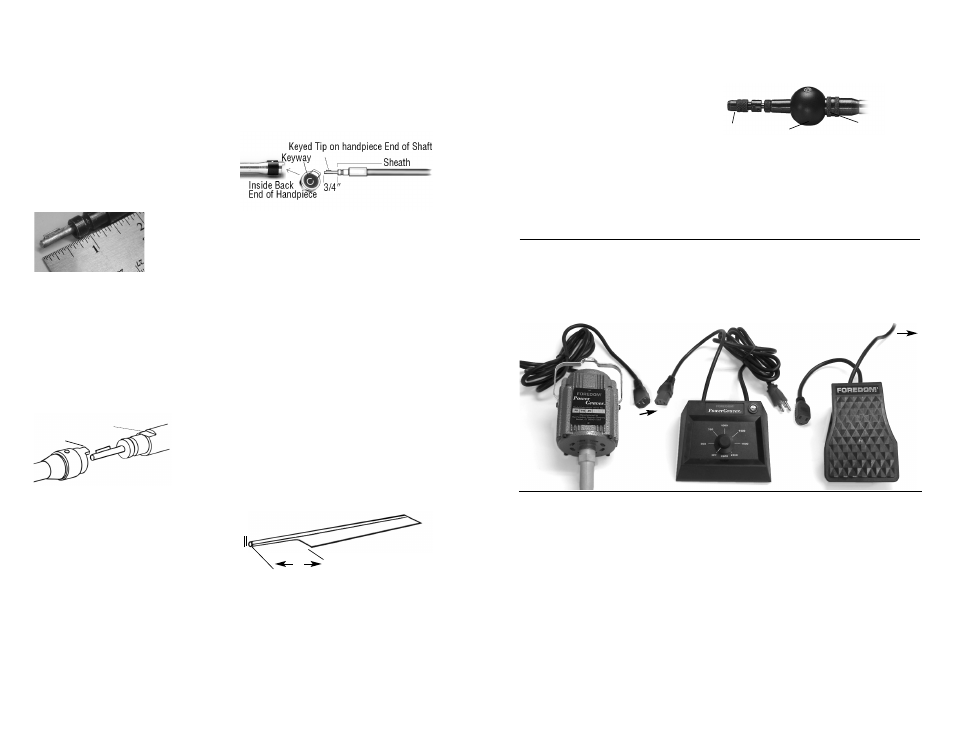
Stroke/Speed Adjustment
The strokes per minute are determined by
motor speed, which can be varied from 500 to
2,800 strokes. Set the speed desired with the
knob on the Variable Speed Dial Control. Both
speed and impact can be adjusted while the
motor is running. The On/Off Foot Switch will
turn the motor on or off at the speed set on the
speed control.
On/Off
Foot
Switch
Optional
Variable
Speed
Dial
Control
Motor
Plug into wall outlet
Plug
into wall
outlet or
Optional
Foot
Switch
3. Plug the Optional On/Off Foot Switch into
an electrical outlet.
5
Connecting Motor and Control
1. Connect male plug of motor to female
cord of Dial Control.
2. Connect male cord of Dial Control into wall
outlet or into female cord of Optional On/Off
Foot Switch.