Gilderfluke&Co 'Dumb' Brick Animation Control System User Manual
Page 31
tern. Note that at frame rates higher than forty FPS, not all 256 channels can be transmitted
through the DMX-512 output.
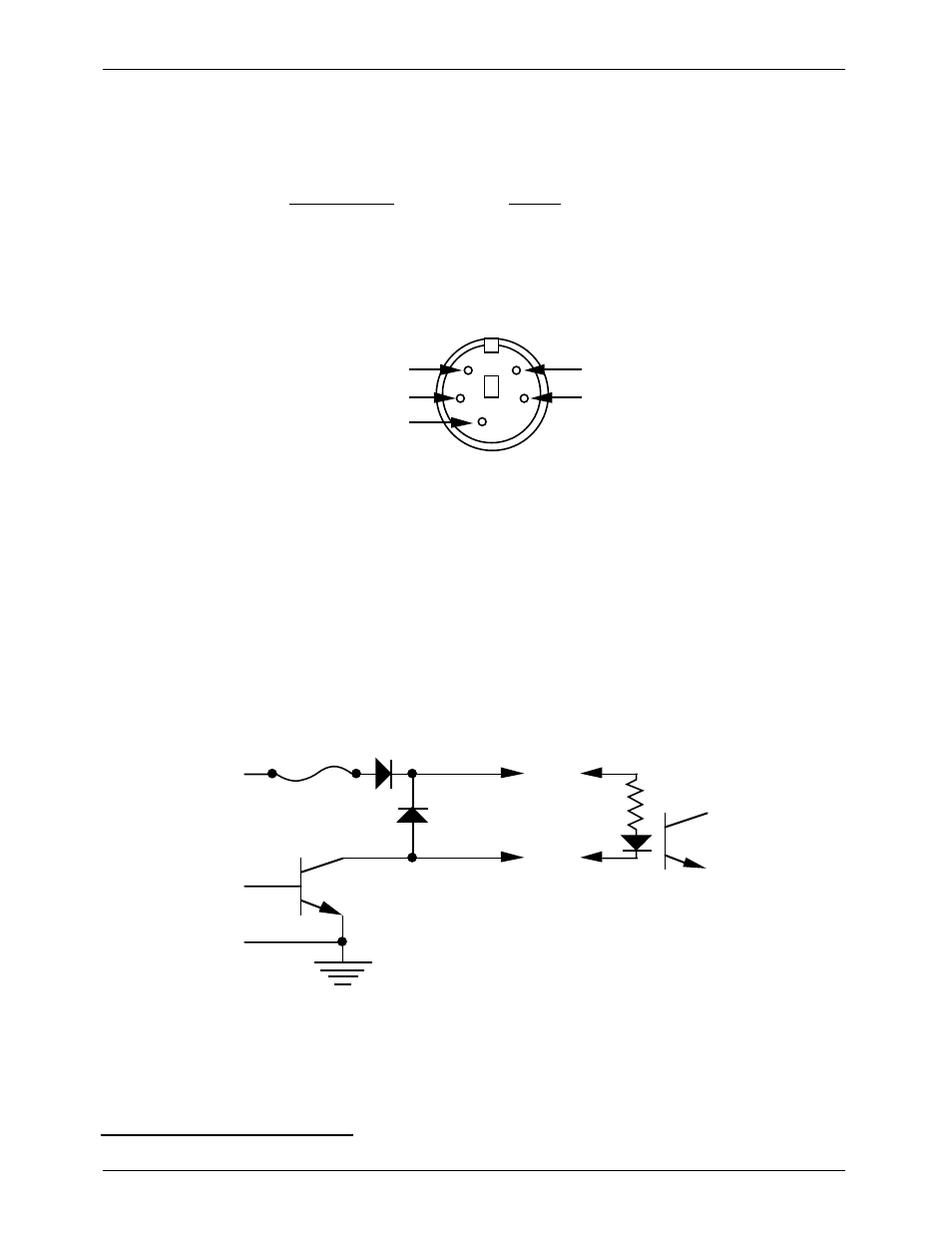
The DMX-512 standard calls out a 5 pin XLR connector for all cabling. Unfortunately these
connectors won't fit on a 1Ó wide card. For this reason we chose a 5 pin MiniDIN connector for
this signal. the pinout is as follows:
MiniDIN pin #
SIGNAL
2
1
Signal Common (shield)
2
Dimmer Drive compliment (Rx Data -)
3
Dimmer Drive True (Rx Data +)
4
Data In True (Tx Data +)
5
Data In compliment (Tx Data -)
Facing the end of the male end of a cable, the pins are located as shown:
Data In True (Tx Data +)
Dimmer Drive Compliment (Rx Data -)
1
2
3
4
5
Dimmer Drive True (Rx Data +)
Data In Compliment (Tx Data -)
signal ground
Data from a PC¥MACs should be fed into pins #2 (-RxD) and #3 (+RxD). The shield
should be connected to pin #1.
The DMX-capable Micro MACs Brick retransmits any DMX-512 data it receives. This data is
unaltered from what came in.
J-6 Digital Output Cables: In all animation systems made by Gilderfluke & Company all input and
output cabling is through what we call ФJ-6Х standard output cables. These are 40 wire cables
which are made up of four identical eight bit wide ÔchannelsÕ. A J-6 cable is often split up into
four individual channels. Each Ô1/4 J-6Õ cable is made up of 10 wires, and can be used to
control eight individual ÔdigitalÕ (off/on) devices, or one eight bit wide ÔanalogÕ device. Each
group of ten wires also includes a common power supply and ground wire.
In all animation systems made by Gilderfluke & Company, all outputs are open collector
switches to ground, and all inputs are opto isolators. Flyback diodes are included in the out-
puts for driving inductive loads:
typical output
typical input
fuse
flyback
diode
supply
supply
To simplify wiring to any MACs animation system, the connectors used on the J-6 cables
are what are called Ôinsulation displacement connectorsÕ. These simply snap on to an entire
cable, automatically ÔdisplacingÕ the wire insulation and making contact with the wires within.
This means that an entire 40 wire cable can be terminated in seconds. All connectors are po-
larized, to keep them from being plugged in backwards. Although there are tools made specif-
ically for installing these connectors, the tool we find works best is a small bench vise.
G
ILDERFLUKE
& C
O
. ¥ 205 S
OUTH
F
LOWER
S
T
. ¥ B
URBANK
, C
ALIF
. 91502-2102 ¥ 818/840-9484 ¥
FAX
818/840-9485
25 of 53
2
Don't blame us for these names. These are directly from the USITT.