Micro macs ôbrickõ connections – Gilderfluke&Co 'Dumb' Brick Animation Control System User Manual
Page 30
- Micro MACs ÔBrickÕ Connections -
J-8 Input: Each Micro MACs Brick features four optically isolated inputs and one optically isolated
status output. The four inputs are used as follows. The colors correspond to those found in six
conductor ÔmodularÕ telephone wire:
A)
Green ÔStartÕ Input
B)
Red ÔStopÕ Input
C) White ÔResetÕ Input
D) Blue ÔExternal ClockÕ or ÔDouble ShowÕ Input
The Yellow ÔRunning StatusÕ output is active whenever the Brick has been Started. It can be
used as a remote Ôshow runningÕ status indicator. These Inputs and Outputs can be configured
to use the same power supply as the rest of the Brick, or an external power supply can be
used.
All the inputs and the one output on the J8 connection are optoisolated. By changing the
position of the jumpers on JP5, you can select whether these optoisolators are powered from
the same power supply as the Brick, or if they are expecting to get power from outside. If they
are running from the same power supply as the Brick, then a simple Ôswitch closureÕ between
the desired input and the BLACK common line will trigger an input. The Micro MACÕs power
supply is protected by a 170 ma. PTC circuit breaker when using internal power.
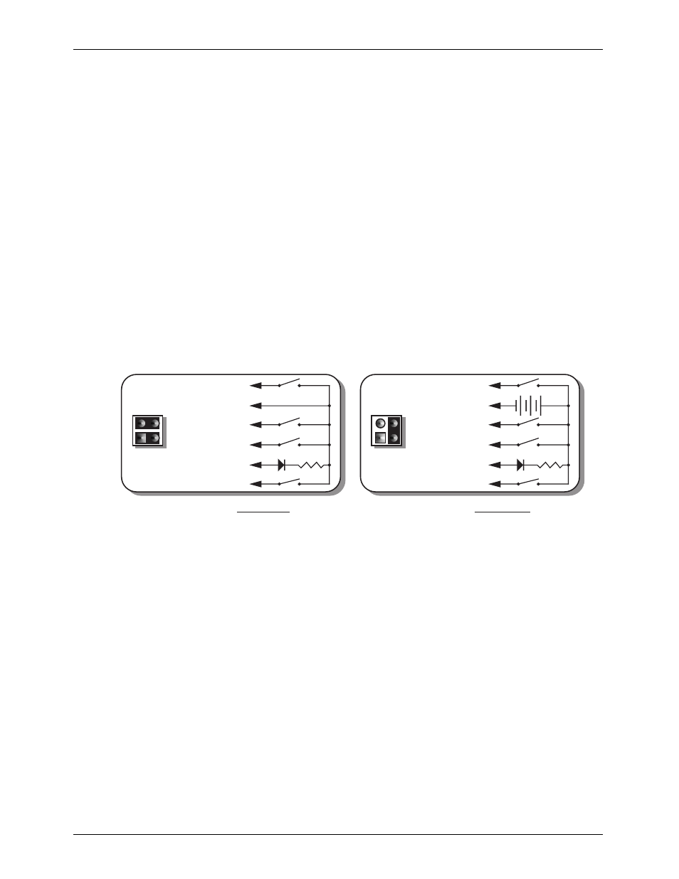
The connections and jumper positions for the J8 port are as follows. As with all RJ-11 (6
conductor modular telephone wire) connections in this manual, all wire colors and numbers
are referenced with you facing the end of the cable with the connector release upwards:
+
+ 12 to 24 VDC SUPPLY
BLUE #6 (clock/dbl show)
YELLOW #5 (status out)
GREEN #4 (start)
RED #3 (stop)
BLACK #2 (common)
WHITE #1 (reset)
2.2K-4.7k
LED
JP-5
2.2K-4.7k
LED
JP-5
J8 with JP5 set for INTERNAL power
J8 with JP5 set for EXTERNAL power
BLUE #6 (clock/dbl show)
YELLOW #5 (status out)
GREEN #4 (start)
RED #3 (stop)
BLACK #2 (common)
WHITE #1 (reset)
If the J8 input is configured to run from an external power source, then you must provide
a 12 to 24 VDC voltage to the BLACK common line. Inputs are then triggered by attaching
them to the ground side of your power supply. This type of Ôswitch to groundÕ output is stan-
dard on most control equipment.
DMX-512: Five pin MiniDIN connector. This connection is available only if the DMX-512 option has
been installed. The DMX-capable Micro MACs Brick will stop listening to the onboard memory
whenever there is a DMX-512 signal present on this input. If Dipswitch #8 is ON, it will never
enable the onboard memory and will always use the most recent DMX-512 data for its out-
puts.
The DMX-512 standard was developed by the United States Institute for Theatrical
Technology (USITT) for a high speed (250 KBaud) asynchronous serial data link. Although it was
originally designed for controlling light dimmers, it is now supported by hundreds of suppliers
throughout the world for controlling all kinds of theatrical equipment.
Even though the DMX-512 standard calls for up to 512 channels of data, the DMX trans-
mission from PC¥MACs is limited to 256 eight bit wide channels. You can address a DMX-
capable Micro MACs Brick to respond to any address between 00 and 255 using the rotary
switches on the front. Addresses above the 256th are used in PC¥MACs for transmitting a
checksum. The DMX-capable Micro MACs Bricks use this to verify that the data received from
PC¥MACs has no transmission errors in it. If you address a light dimmer or other DMX-512 de-
vice to addresses 256 or 257, you will see this verification data displayed as a flickering pat-
G
ILDERFLUKE
& C
O
. ¥ 205 S
OUTH
F
LOWER
S
T
. ¥ B
URBANK
, C
ALIF
. 91502-2102 ¥ 818/840-9484 ¥
FAX
818/840-9485
24 of 53