Tools – Securitron LMD-1 User Manual
Page 2
PN#
500-18400
Page
2
Rev. C, 2/09
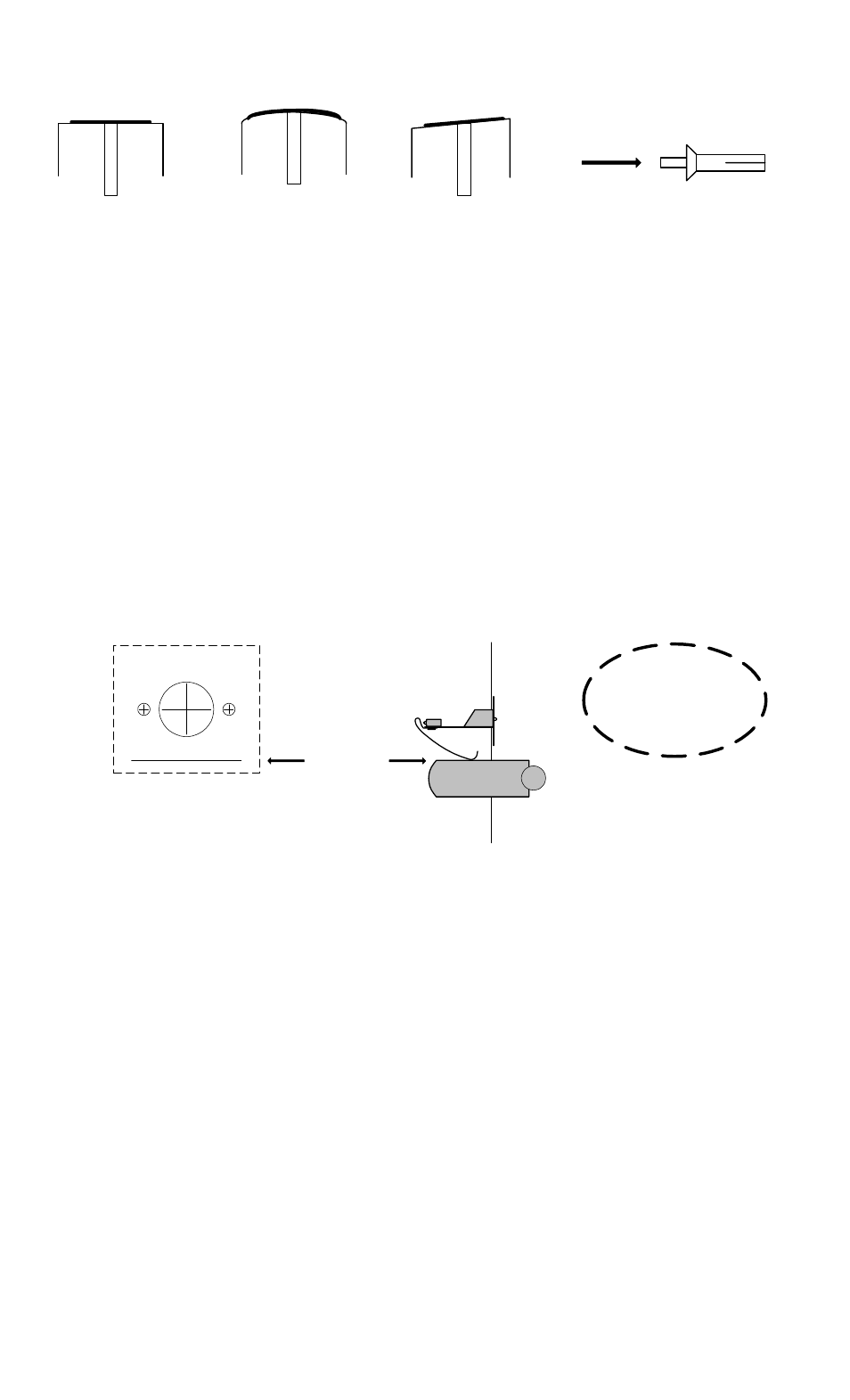
FIG. 2: MOUNTING IN FLAT, CURVED OR ANGLED FRAMES AND USE OF DRIVE RIVETS
FOR FLAT FRAME FACE (LEFT), UNIT INSTALLS NORMALLY.
FOR CURVED FRAME FACE (CENTER), THE MOUNTING PLATE
WILL BEND TO FOLLOW THE CURVE. FOR ANGLED FRAME
FACE (RIGHT) BEND THE PROJECTING BRACKET SLIGHTLY AS
SHOWN SO THAT IT FITS INTO THE CENTER OF THE FRAME
STILE
USE OF DRIVE RIVETS
INSERT LARGE END OF RIVET
THROUGH LMD MOUNTING
PLATE INTO HOLE IN FRAME.
TAP WITH HAMMER FROM THE
DIRECTION SHOWN BY THE
ARROW TO SEAT THE RIVET.
3. OPERATION
Finally note that tampering or mechanical failure of the unit is possible. For best system
reliability therefore, the unit should be periodically tested to confirm that the output changes
state as the Deadlock seats and is opened.
4. WIRING
The Deadlock Monitor has three wires (SPDT, form C) that are assigned by color as follows:
White = Common
Red = N.C.
Blue = N.O.
Because we’re using the terms normally open and normally closed, it’s necessary to define what
we mean by “normal”. The normal condition of the Deadlock Monitor is when it is
reporting secure (the door is locked). So, for example, you’ll read a closed circuit between
White and Red if you meter the unit in the secure condition but you’ll read open if you meter it
in the alarm condition (door is open). Maximum contact ratings are 2 Amps at 24V.
LINE IS EVEN WITH TOP OF BOLT
9/16" DIA
1/8" DIA
1/8" DIA
TEMPLATE
CENTER HOLES ON FRAME
CUT OUT TEMPLATE ON
DOTTED LINE
ALIGNMENT
TOOLS:
1/2" DRIVE DRILL
1/8" (3MM) BIT
9/16" (15MM) BIT
HAMMER