Securitron LMD-1 User Manual
Securitron For Home
Securitron Magnalock Corp.
Tel 775.355.5625
550 Vista Boulevard
Fax 775.355.5633
Sparks, NV 89434
www.securitron.com
© Copyright, 2009, all rights reserved
PN# 500-18400
Page
1
Rev.
C,
2/09
ASSA ABLOY, the global leader
in door opening solutions
SECURITRON MODEL LMD-1 DEADLOCK MONITOR
INSTALLATION AND OPERATING INSTRUCTIONS
1. DESCRIPTION
The Deadlock Monitor is employed with an Adams Rite MS type deadlock or similar lock from
an alternate manufacturer to report on the locked or unlocked status of a narrow stile door
(usually aluminum frame glass). The LMD-1 provides an SPDT dry output to an alarm system
or other monitoring device. It provides higher security assurance than the more commonly
employed magnetic contacts which report a door as “closed” when it may still be unbolted. The
LMD-1 installs easily in the door frame stile without the need for any routing.
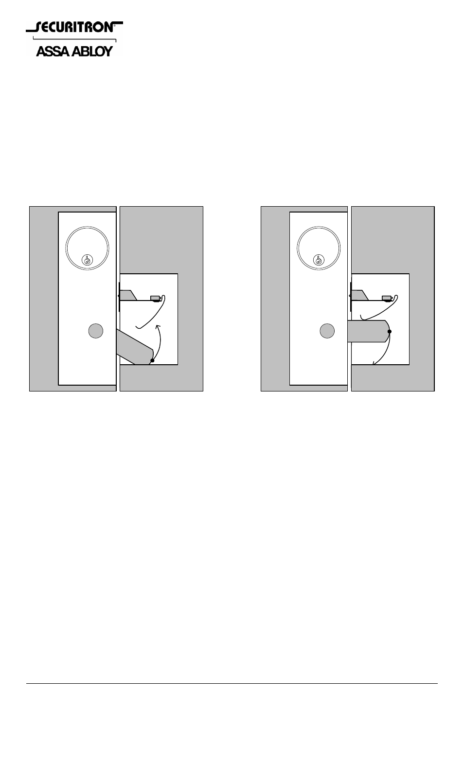
FIG. 1: LMD OPERATION WITHIN THE DOOR FRAME STILE
2. PHYSICAL INSTALLATION
The LMD-1 is installed within the door frame such that as the bolt moves into the secure
position, the curved trigger is deflected. There is a lot of “margin for error” in the amount of
deflection because as soon as the curved trigger moves, the switch will change state. Figure 1
shows how this works. A benefit of the LMD-1’s design is that when the door is locked, the
trigger assembly is not touching the switch so that aggressive rattling of the door will not affect
the switch.
You will drill three holes following the template (see back page) to mount the Deadlock Monitor.
To set your vertical position for the template on the door frame stile, close the door and
throw the Deadlock. Mark the level on the frame even with the top of the bolt. This is the
point at which you place the line on the template. Center the template on the face of the frame
and drill the three holes as shown. The central hole is 9/16” (15 MM) in diameter and the
outer holes are 1/8” (3 MM) in diameter. After you drill the 9/16” hole, rock the drill bit up
and down vertically to make the hole somewhat oval shaped. Once you have drilled the holes,
check if the door frame face is curved or angled as opposed to flat (see Figure 2). If it is
curved, the LMD’s mounting plate is made thin enough so that it will bend to follow the curve. If
the frame face is angled, you can bend the mounting plate with respect to the projecting bracket
which holds the switch to correct for the frame face angle. Then, after you have connected
your wires and pulled them up the door frame, push the unit into the 9/16” diameter hole by
first collapsing the trigger in your hand (it will spring out again when the unit is in the hole).
The unit is secured by pushing the supplied drive rivets into the outer holes and tapping them
flush with a hammer. If, subsequently, the unit has to be replaced, use a center punch to drive
the central pin all the way through the rivet. The rivet can then be rocked out with a knife
blade.