Securitron iMXDa_iEXDa QUICK START GUIDE User Manual
Page 4
PN# 500-22310
Page 4
Rev. B, 01/10
11.Assemble the lock back onto the mounting bracket, then using a 3/32” hex wrench tighten
the three (3) set screws along the upper/back side of the unit to secure.
12.Check lock mount assembly for adequate tightness and secure installation.
13.Make wire connections, apply power and test for proper operation. Refer to Sections 6.7
and 6.8 of the Installation and Operating Manual.
14.After completing wiring and testing, ensure that the three (3) set screws in the top/rear of
the lock housing are tight and the lock is secure, and then insert the provided dress plugs
into the lock set screw and the actuator mounting holes.
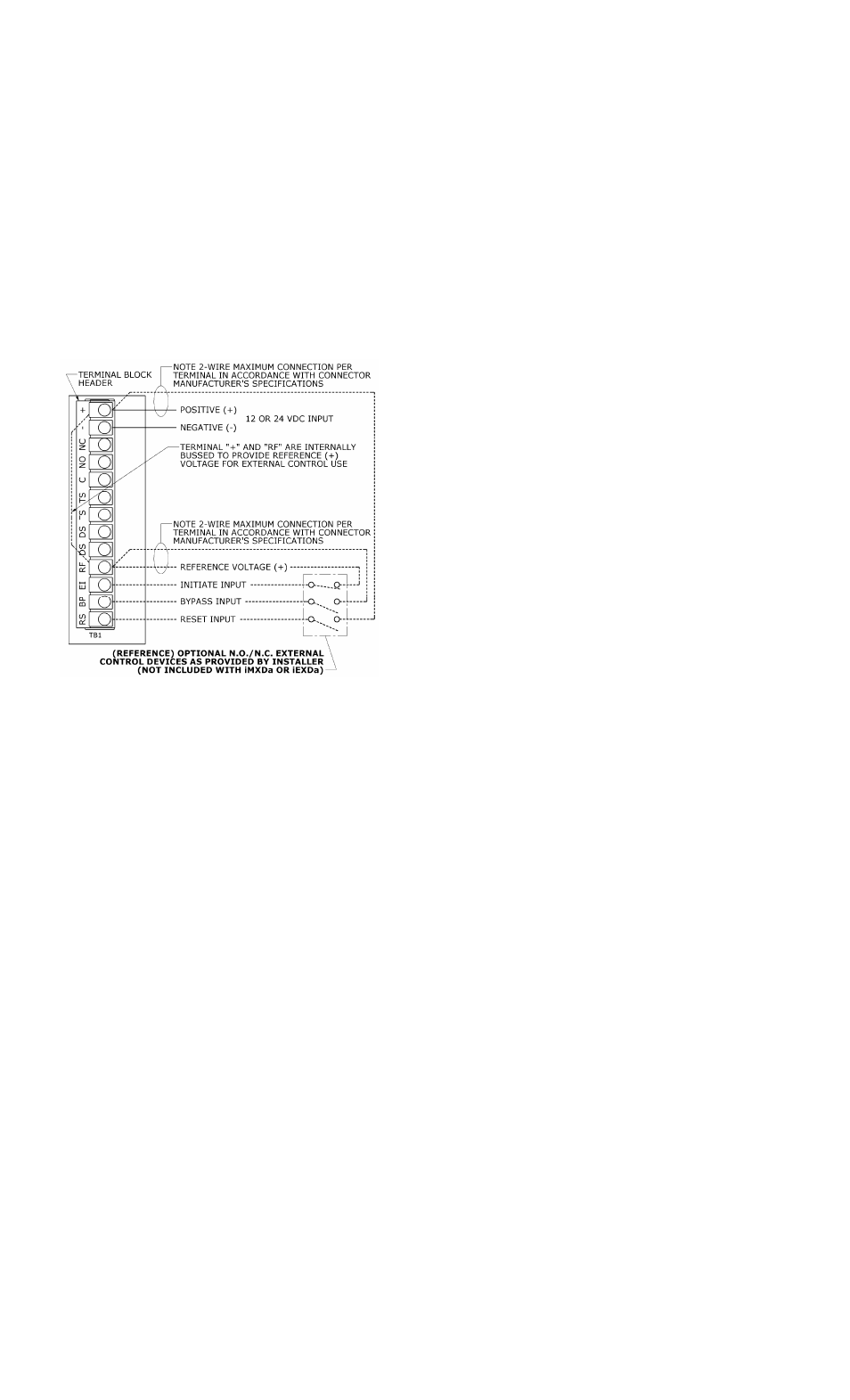
STEP 3 - CONTROL WIRING
Figure 5 is a general wiring diagram that shows the terminal block layout and some typical
control wiring for an iMXDa/iEXDa. It is suggested that an adequate wire service loop be
provided to allow easy connect/disconnect of the plug-in terminal block connector.
External Controls:
Each unit includes terminals which provide the
connections necessary for remote control of
specific functions such as reset, bypass and
external initiate. These are addressed in Section
6 of the Installation and Operating Manual.
Notes:
1) To operate the external initiate (iEXDa) the
jumper JP3 must be placed over pins 1 and 2.
2) The “RF” terminal is a common reference
(+) voltage supply point that may be used
for the above described external controls.
Tamper Status (TS) and Door Status (DS):
The door and tamper status switches provide dry
contact output at the terminal block header.
Output is field selectable via jumpers (JP1 and
JP2).
The factory jumper settings are set for
normally closed operation.
Figure 5
Control Wiring
NOTE: For more information regarding electrical
wiring and operation of the unit please refer to the
Installation and Operating Instruction Manual.
FUNCTION SETTINGS
A wide variety of functions are set/controlled by the internal PC board mounted DIP switch. For
full details regarding DIP switch function settings please see the Installation and Operating
Instruction Manual.