Securitron PB2 User Manual
Page 2
PN# 500-23140
Page 2
Rev. C, 08/11
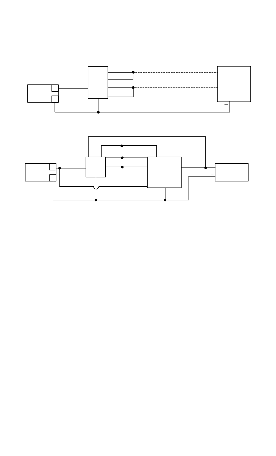
Momentarily pressing the button will release the lock for the amount of time set on the
TimeMate. The indicator will change colors during the lock release period. The wiring is also
done in double break fashion so that even if the timer fails, the button will still be able to
momentarily release the lock. This is for added safety.
POWER
SUPPLY
TIMEMATE
+
YELLOW
RED
WHITE
BLACK
D.C. LOCK
FAIL SAFE
GREEN
PB2
+
BLUE
RED
BLACK
BLUE
YEL
L
O
W
GR
E
E
N
POWER
SUPPLY
+
D.C. LOCK
ELECTRIC
PB2
+
WHITE
BLUE
RED
BLACK
+
GREEN
YELLOW
IF FAIL SAFE
IF FAIL SECURE
MOMENTARY RELEASE OF FAIL SAFE OR FAIL SECURE ELECTRIC LOCK
TIMED DOUBLE BREAK RELEASE OF FAIL SAFE LOCK
WHITE
5. ALTERNATE LENS CHANGING
The pushbutton is factory shipped with the green lens set installed and two lens/insert options.
Changing to the other lens sets is simple.
1) Grasp keyplate and turn over. From the back rotate the white contact block of the switch
counter-clockwise to the 11 o’clock position and pull straight back to remove the contact
block.
2) With a slender smooth ended object such as a marker pen, slide it inside the switch body
until it stops against the back of the lens. Place the object that is inside the switch body on a
smooth surface with the keyplate on top, and tap the keyplate up and down on the object to
pop the lens off. Remove the lens and insert.
3) Turn the keyplate over and place the new insert onto front of switch, confirm that the text on
the insert is correct reading to the keyplate and place the matching colour lens on top of the
insert and compress around all edges of the lens until it snaps in place. Depress lens several
more times to ensure smooth operation and that the lens is not binding.
4) With the terminals upward insert the contact block back into the back of the switch at the 11
o’clock position and rotate clockwise until it stops straight up and down.
6. LED REPLACEMENT
The switch LED is replaced by grasping the back of the white contact block and twisting it
counter-clockwise to the 11 o’clock position, pull the contact block straight out of the rear of the
switch. This reveals the LED which then can be pulled out from the block. Note: LED is polarity
sensitive. Insert new LED into contacts, the
marking on the LED should be on the same side
as the green wire with printing facing the same directions as the switch block terminals.
Operating Life of the switch LED is 100,000 hours. Reverse step to lock contact block back into
switch body.