Securitron PB2 User Manual
Securitron For Home
Securitron Magnalock Corp.
www.securitron.com
ASSA ABLOY, the global leader
Tel
800.624.5625
in door opening solutions
© Copyright, 2011, all rights reserved
PN# 500-23140
Page 1
Rev. C, 08/11
SECURITRON PB2 SERIES EXIT BUTTON
INSTALLATION AND OPERATING INSTRUCTIONS
1. DESCRIPTION
The model PB2 is a spring loaded momentary 2" square, exit button, mounted on a stainless
steel single gang outlet box cover. The SPDT contacts switch when the button is depressed and
return when it is released. The contacts are UL listed with 5 AMP capacity. The indicator LED is
mounted above the button and the switch LED illuminates the button itself.
The indicator LED and switch LED can be individually operated according to the needs of the
installation. The PB2 can be used for momentary release of fail safe or fail secure electric locks.
If interfaced with a release hold timer, such as Securitron's TimeMate, it can provide for timed
release of electric locks. It may also be used to input a REX (request to exit) signal to a card
reader system. We recommend that the local building or fire safety authority be consulted prior
to using exit buttons for door egress. They may require a "no special knowledge" exit device
such as Securitron's Touch Sense Bar.
2. INSTALLATION
The PB2 comes with a plastic mounting device and color coded hookup wires installed. If a
enclosed box is used, be sure it is at least 2 1/2" deep to accommodate the switch. The
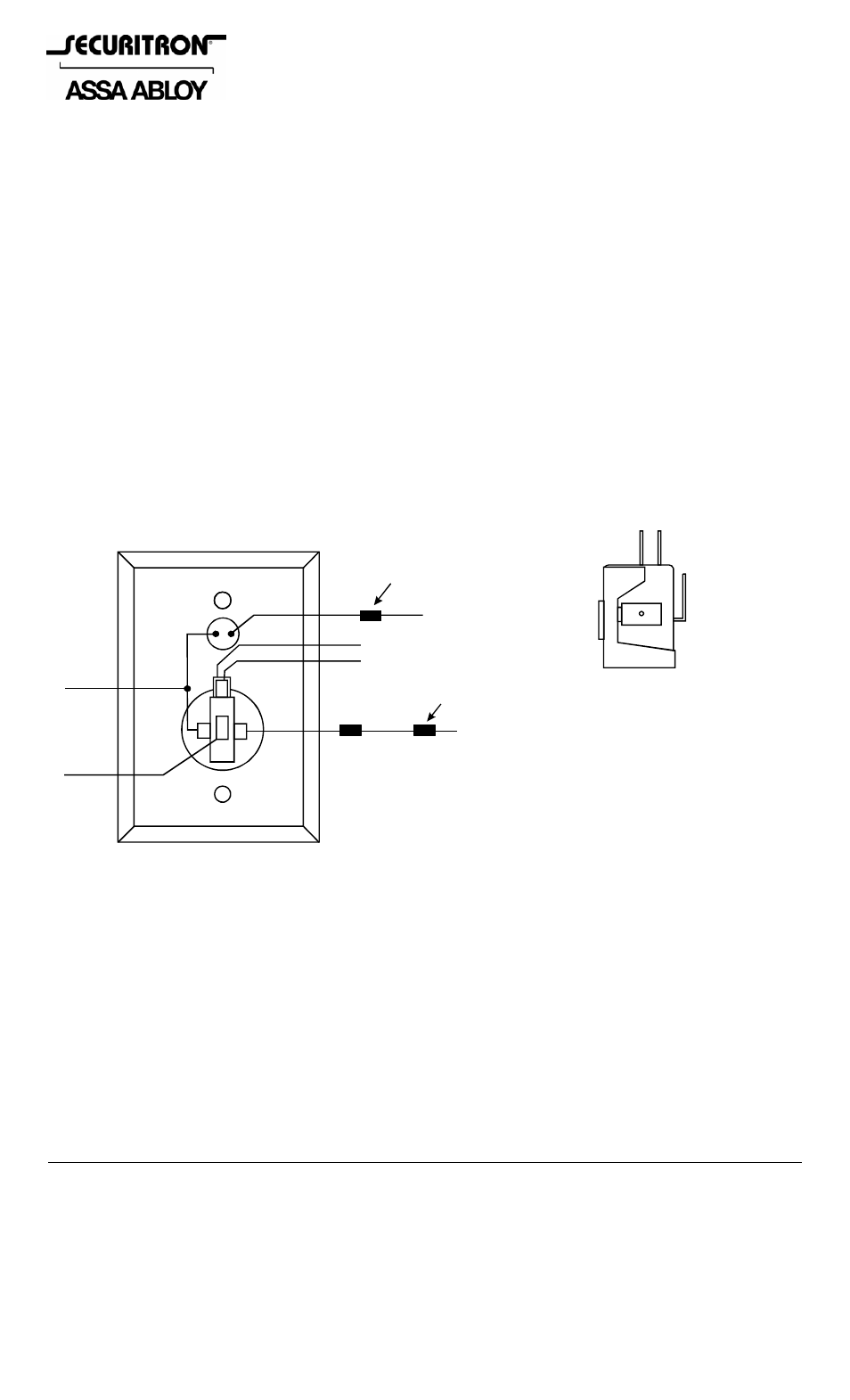
drawings below show identification of the unit's connection points.
WIRE IDENTIFICATION
WHITE
REAR OF UNIT SHOWN
GREEN
YELLOW
BLACK
INDICATOR
LED
RED
BLUE
REMOVE RESISTOR FOR
12 VDC OPERATION
REMOVE OUTER RESISTOR
FOR 12 VDC OPERATION
NOTE: LIGHTS OPERATE
ON 24 VDC IF RESISTORS
ARE NOT REMOVED
YELLOW = INDICATOR LED POSTIVE
GREEN = SWITCH LED POSITIVE
BLACK = COMMON DC NEGATIVE
RED =
BLUE =
SWITCH N.C.
SWITCH N.O.
WHITE = SWITCH COMMON
1.2 K
1/4W
620 OHM
1/4W
COM
N.O.
N.C.
TERMINAL TYPE
.250” QUICK CONNECT
Figure 1
3. LED OPERATION
Resistors are installed so that the LEDS may be operated on either 12 or 24 VDC. The yellow
wire drives the indicator LED and the green wire drives the switch LED. Both wires have
resistors soldered on them. If the power supply is 24 VDC, connect directly to the wires. If the
power supply is 12 VDC, remove the resistor for proper operation at the lower voltage. See
Figure 1. The indicator LED draws 20 mA and the switch LED draws 9 mA @ 12VDC or 20 mA @
24VDC.
4. WIRING
The PB2 can be used in many different ways but the drawings below show two common
applications. The first shows momentary release of a fail safe or fail secure electric lock. The
PB2 indicators are connected so that the switch LED is normally on. When the button is pressed,
releasing the lock, the switch LED turns off and the indicator LED comes on. The second
drawing shows timed release of a fail safe electric lock using the PB2 and Securitron's TimeMate.