Securitron HHSR User Manual
Page 5
PN# 500-16600
Page 5
Rev. D, 07/11
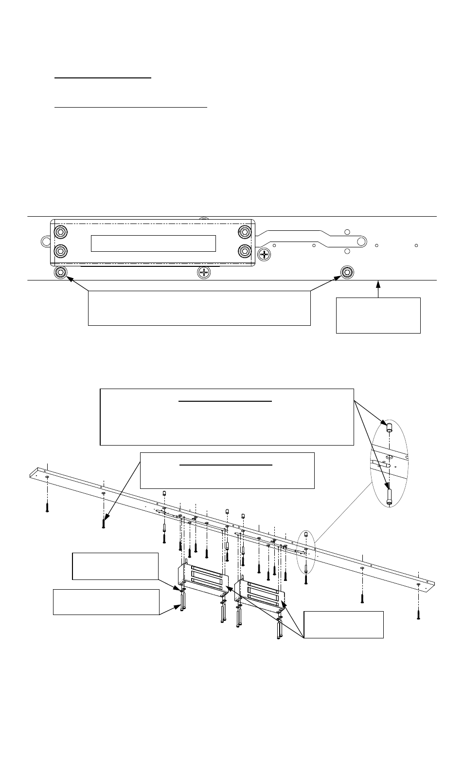
Once the mounting plate is suitably positioned, it may be used as a template to mark/drill the
holes required in the door frame.
FOR WOOD FRAMES:
Drill 3/16” [4.8] diameter x 1-1/4” [31.8] deep holes for wood door frame mounting.
FOR STEEL/ALUMINUM FRAMES:
Drill 3/8” [9.5] diameter holes through for each blind nut installation. (See the Magnalock
installation instructions for detailed information on installing the blind nuts).
Drill 3/16” [4.8] diameter holes for each remaining bracket mounting hole.
Secure the mounting plate to the door frame using the provided hardware. NOTE: WHEN
INSTALLING THE MOUNTING PLATE TO STEEL OR ALUMINUM DOOR FRAMES - USE OF
1/4-20 X 1” [25.4] SHCS AND BLIND NUT IS HIGHLY RECOMMENDED AT TWO (2)
HOLE LOCATIONS ADJACENT TO EACH LOCK MOUNTING POSITION AS SHOWN IN
FIGURE 6.
Figure 6
As an example, the following illustrations show the exploded assemblies of the Magnalock
mounting (Figure 7) and the cover assembly (Figure 8) on a typical HHD-62 model full length
housing.
Figure 7
FOR METAL FRAMES:
USE (2) 1/4-20 X 1” [25.4] SHCS + BLIND NUT AT THE
FORWARD MOUNTING HOLES ADJACENT TO EACH LOCK
MOUNT POSITION AND #12 X 1-1/2” [38.1] SMS/WOOD
SCREWS AT EACH REMAINING MOUNTING HOLE
MAGNALOCK(S)
(Not Included)
FLAT WASHERS
(Not Included)
1/4-20 MAGNALOCK
MOUNTING SCREWS
FOR WOOD FRAMES:
USE #12 X 1-1/2” [38.1] SMS/WOOD
SCREWS AT EACH MOUNTING HOLE
FORWARD
(DOOR) SIDE OF
MOUNTING BASE
RECOMMENDED HOLES FOR BLIND NUT
INSTALLATION ON STEEL OR ALUMINUM FRAMES
- TWO (2) AT EACH MAGNALOCK LOCATION
(REF.) M62 MAGNALOCK