Terminal descriptions, Slimzone deluxe 26 – Robertshaw SlimZone Deluxe ZONE CONTROL SYSTEM User Manual
Page 30
SlimZone Deluxe
26
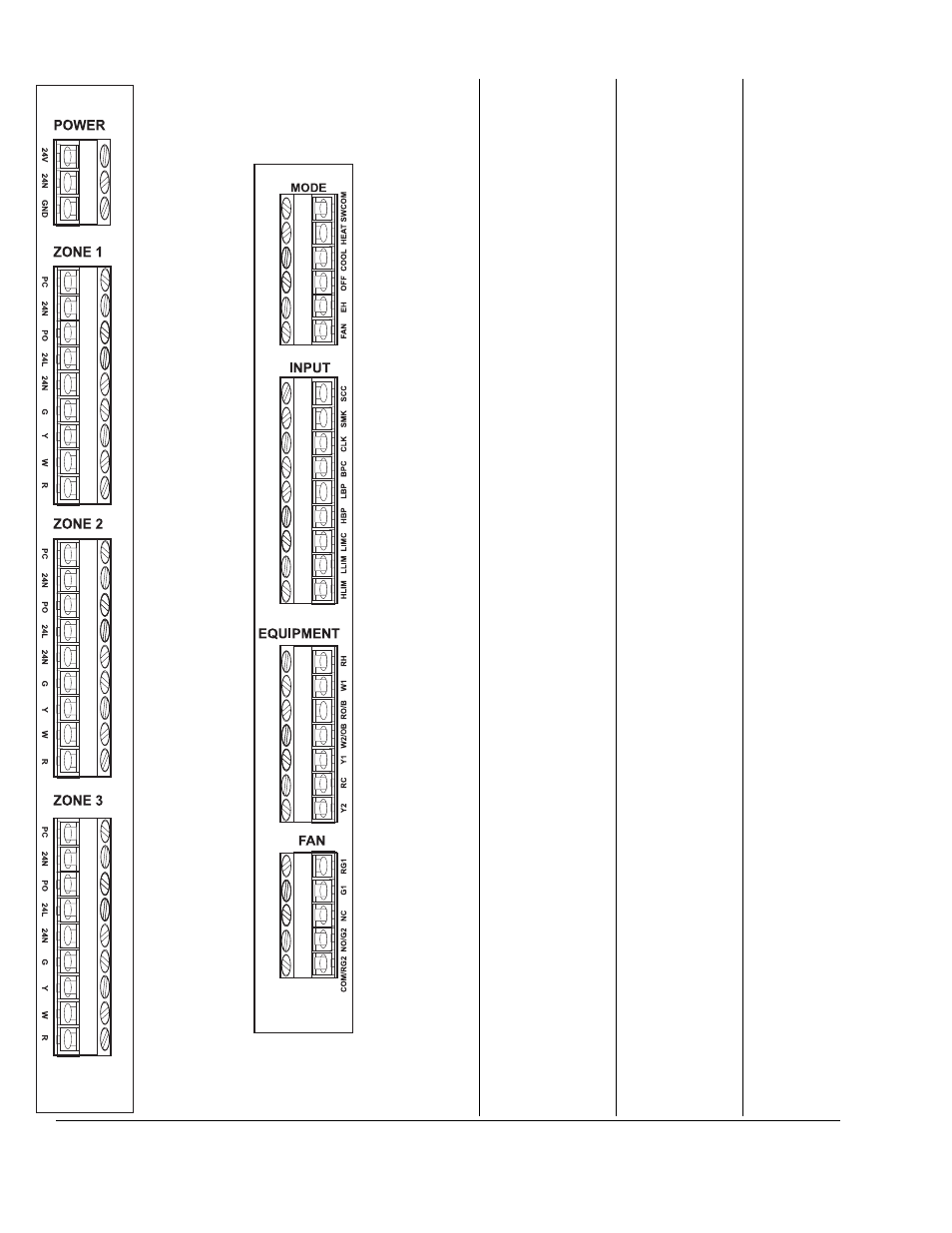
POWER
24V
Live connection from
the 24VAC trans-
former to power the
panel.
24N
Neutral or common
connection from the
24VAC transformer.
GND
To be connected to a
good electrical earth
ground.
ZONES 1-3
PC
Power close terminal
for the damper.
24N
Neutral or common
connection for the
damper. Inside the
SZD it is connected
to the 24N terminal
of the zone 24VAC
transformer.
PO
Power open terminal
for the damper.
24L
Live connection from
the zone 24VAC
transformer to power
the damper.
24N
Neutral or common
connection from the
zone 24VAC
transformer.
G
Connected to the fan
output of the zone
thermostat. The SZD
will react to an
electrical connection
between G and R as
a call for fan from the
specific zone.
Y
Connected to the
cool output of the
zone thermostat. The
SZD will react to an
electrical connection
between G and Y as
a call for cool from
the specific zone.
W
Connected to the
heat output of the
zone thermostat. The
SZD will react to an
electrical connection
between G and W as
a call for heat from
the specific zone.
R
Connected to the R
terminal on the zone
thermostat. Internally
in the SZD it is
connected to 24N
terminal of the
specific zone.
MODE
SWCOM
The terminal is
shared by all the
mode inputs.
Internally it is
electrically connect-
ed via the 2.5Amp
poly-fuse to the 24N
terminal of the power
terminal block.
HEAT
The SZD will react to
an electrical
connection between
this terminal and
SWCOM as a
request to switch into
the heat only mode.
COOL
The SZD will react to
an electrical
connection between
this terminal and
SWCOM as a
request to switch into
the cool only mode.
OFF
The SZD will react to
an electrical
connection between
this terminal and
SWCOM as a
request to switch into
the OFF mode.
EH
The SZD will react to
an electrical
connection between
this terminal and
SWCOM as a
request to switch into
the emergency heat
mode.
FAN
The SZD will react to
an electrical
connection between
this terminal and
SWCOM as a
request for a system
wide continuous fan.
INPUT
SCC
This is the common
terminal shared by the
smoke and clock
inputs. Internally it is
electrically connected
via the 2.5 Amp poly-
fuse to the 24N
terminal of the power
terminal block.
SMK
The SZD will react to
an electrical connection
between this terminal
and SCC as if smoke
were detected by the
smoke detector.
CLK
The SZD will react to
an electrical connection
between this terminal
and SCC as if the clock
were switched into the
unoccupied mode.
BPC
This is the common
terminal shared by the
HBP and LBP inputs.
Internally it is electrical-
ly connected via the 2.5
Amp poly-fuse to the
24N terminal of the
power terminal block.
LBP
The SZD will react to
an electrical connection
between this terminal
and BPC as if the out-
door temperature were
below the low balance
point.
HBP
The SZD will react to
an electrical connection
between this terminal
and BPC as if the out-
door temperature were
above the high balance
point.
LIMC
This is the common
terminal shared by the
LLIM and HLIM inputs.
Internally it is electrical-
ly connected via the
2.5Amp poly-fuse to
the 24N terminal of the
power terminal block.
LLIM
The SZD will react to
an electrical
connection between
this terminal and LIMC
as if the temperature in
the duct were below
the low limit.
HLIM
The SZD will react to
an electrical connection
between this terminal
and LIMC as if the tem-
perature in the duct
were above the high
limit.
FAN
RG1
Connected to the R
terminal on the fan.
This terminal can be
electrically discon-
nected from
COM/RG2 by
removing the shunt
positioned at the
bottom of this termi-
nal block.
G1
When the Deluxe
panel calls for fan or
first stage of fan, it
electrically connects
the G1 terminal to
the RG1 terminal.
NC
This terminal normal-
ly is used only in the
economizer system.
In the default mode
it is electrically
connected to the
COM/RG2 terminal.
NO/G2
This terminal can be
configured by DIP
switch numbers 1, 2
and 3 of SW6 as an
output to an econo-
mizer. In the default
mode it is electrically
disconnected from
the COM/RG2
terminal. If this
terminal is used as a
second stage output
to a fan it will be
electrically connect-
ed to COM/RG2
whenever the panel
calls for a second
stage fan.
COM/RG2
Used as the common
terminal for the
economizer or the R
terminal for the sec-
ond stage fan. This
terminal can be elec-
trically disconnected
from RG1 by remov-
ing the shunt posi-
tioned at the bottom
of this terminal block.
EQUIPMENT
RH
Connected to the R
terminal from the
heating equipment.
This terminal can be
electrically discon-
nected from RO/B by
removing the shunt
positioned at the top
of this terminal block.
W1
When the Deluxe
panel calls for heat it
electrically connects
the W1 terminal to
the RH terminal.
RO/B
Connected to the R
terminal from the
reversing valve. This
terminal can be elec-
trically disconnected
from RH by removing
the shunt positioned
at the top of this
terminal block.
W2/OB
In the case of a two
stage conventional
heating system this
terminal will be elec-
trically connected to
the RO/B terminal
when there is a call
for second stage
heat. If the system is
configured as a heat
pump system and
depending on the set
up of DIP switch
number 2 of SW4,
this terminal will be
connected to RO/B
when the heat pump
is switched it either
cool (O) or heat (B)
mode.
Y1
When the Deluxe
panel calls for first
stage of cool or a
first stage of heat in
a heat pump system,
it electrically con-
nects the Y1 terminal
to the RC terminal.
RC
Connected to the R
terminal on the cool-
ing or heat pump
equipment.
Y2
When the Deluxe
panel calls for sec-
ond stage of cool or
a second stage of
heat in a heat pump
system, it electrically
connects the Y2
terminal to the RC
terminal.
24. TERMINAL DESCRIPTIONS