Robertshaw SlimZone Deluxe ZONE CONTROL SYSTEM User Manual
Page 23
SlimZone Deluxe
19
Robertshaw SlimZone Deluxe
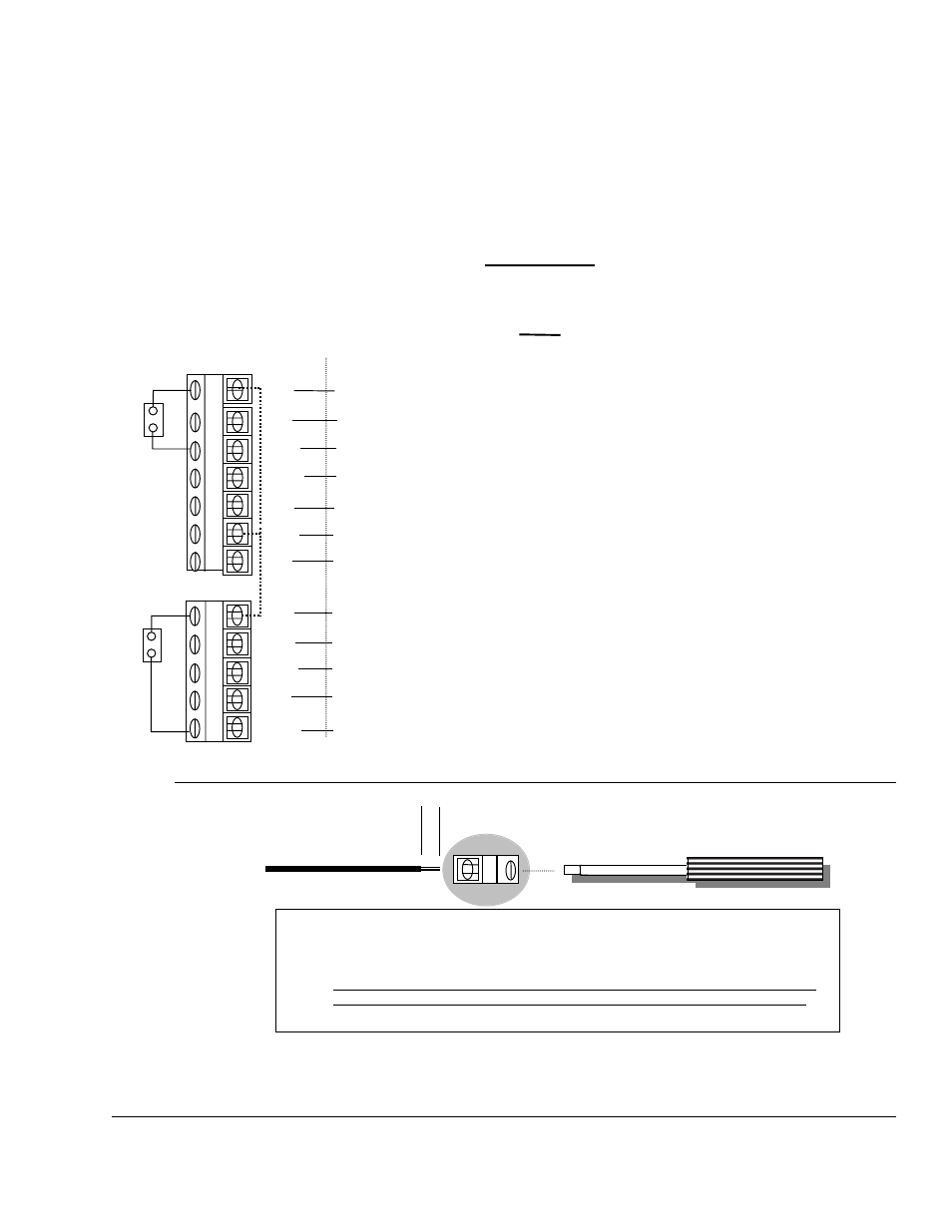
Master Logic Panel
EQUIPMENT
Detail E
and
FAN
Detail F
1/4”
NOTE: Use standard nonshielded 18-24 AWG copper wire for all terminal landings.
Strip wire insulation no more than 1/4” and after landing wire to designated
terminal, use a proper sized flat bladed screwdriver to secure the wire.
CAUTION! Do not use excessive force when tightening the terminal screws as
terminal block connections to the printed circuit board could crack or break.
18-24 AWG copper wire
RH
W1
RO/B
W2/
OB
Y1
RC
Y2
Connected to the equipment (R) transformer terminal. RH can be disconnected from
ROB by removing the shunt positioned at the top of the EQUIPMENT Terminal Block.
Connected to the equipment (W1) heat terminal.
Connected to the O or B terminal on a heat pump controlling the reversing valve.
Connected to the equipment (W1) terminal or the O/B second stage heat pump
terminal.
Connected to the equipment (Y1) cool terminal.
Jumper to RH for single equipment transformer or connect to cooling transformer (R).
Connected to the equipment (Y2) terminal or the second stage heat pump
compressor terminal.
RG1
G1
NC
NO/
G2
COM/
RG2
EQUIPMENT
FAN
Connected to the (R) terminal on the equipment. RG1 can be disconnected from
COM/RG2 by removing the shunt located at the bottom of the terminal block. Must be
jumpered to RC if fan does not have 24 Volt power supplied.
Connected to the equipment (G1) fan terminal.
This terminal is used for an economizer system. Default mode electrically connects NC to
COM/RG2.
This terminal is configured by switch number 1, 2 and 3 on SW6 as an economizer
output. Default mode electrically disconnects NO/G2 from COM/RG2.
Used at the common terminal for economizer or the R terminal for the second stage fan.
Terminal can be electrically disconnected from RG1 by removing the shunt located at
the bottom of the terminal block.
JP1
JP2
17. LOGIC PANEL EQUIPMENT AND FAN TERMINAL DESIGNATIONS