Figure 1 figure 2 – Reese 30156 MOUNTING KIT ADAPTER User Manual
Page 2
© 2011 Cequent Performance Products, Inc. Made in XXX
30156N
08-08-11
Rev. A
1. SYSTEM ASSEMBLY
P. 2
2. SYSTEM ADJUSTMENT
P. 3
3. INSTALLATION
P. 3
4. REMOVAL
P. 4
5. BEFORE EACH TRIP/LUBRICATION
P. 4
6. LIMITED LIFETIME WARRANTY P. 5
WARNING:
Failure to follow all of these instructions may result in death or serious injury
INDEX
SYSTEM ASSEMBLY
REQUIRED TOOLS
•
1 ½” SOCKET AND MATCHING WRENCH (OR CRESENT WRENCH)
•
RUBBER MALLET
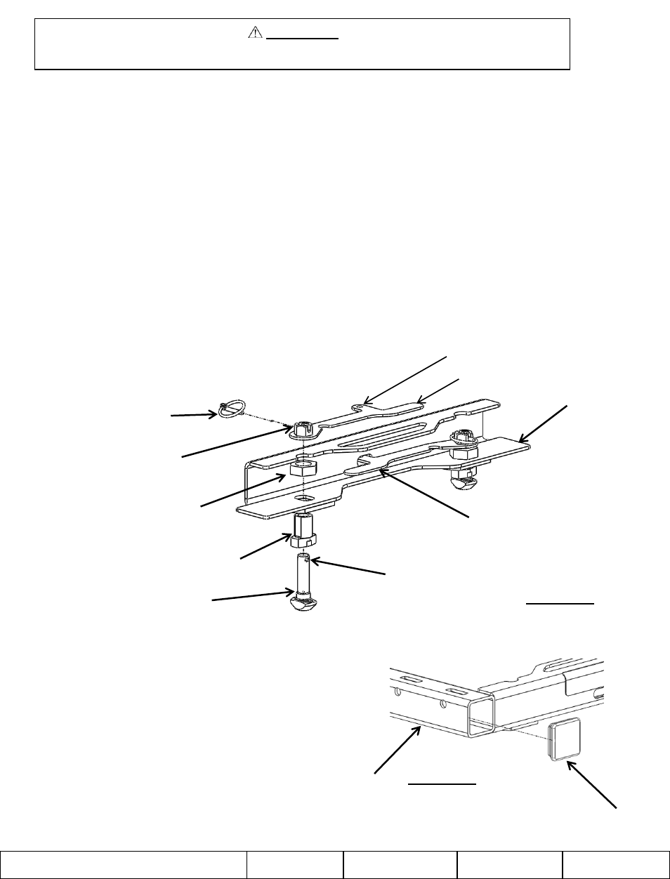
TEE PIN AND BUSHING ASSEMBLY
1. Assemble the four anchor bushings and the 1” jam nuts together (fig 1) and snug-fit (no vertical play in anchor bushing
assembly), then go another quarter turn beyond contact point for proper torque requirement.
2. Once all of the bushings and jam nuts are tight, assemble the tee pin and handle as shown (fig 1). (NOTE) When handles are
in locked position locking tab must protrude through slot in channel.
3. Tighten tee pin until there is metal to metal contact. Once this is accomplished loosen tee pin one-and-a-half rotations.
4. Align hole in tee pin and slot in handle nut, pin with included lynch pin.
5. Repeat steps 2, 3, 4 for remaining anchor bushings.
CHANNEL
HANDLE IN LOCKED POSITION
TEE PIN
ANCHOR BUSHING
1” JAM NUT
HANDLE
SLOT IN HANDLE NUT
HOLE IN TEE PIN
FIGURE 1
FIGURE 2
1. Orient end cap as shown (fig 2), with ribs being inserted into
cross tube.
2. Insert end cap until flanged surface contacts edge of tube.
3. Repeat steps 1 and 2 for remaining end caps.
End Cap Installation
LOCKING TAB
LYNCH PIN
END CAP
CROSS TUBE
SHEET 2 OF 5