Reese 30154 MOUNTING KIT ADAPTER User Manual
Page 3
© 2013 Cequent Performance Products, Inc. Printed in Mexico
30154N
06-24-13
Rev. A
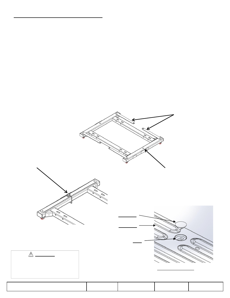
REESE Fifth Wheel Mounting Adapter Adjustment
The REESE mounting kit adapter is pre-assembled to fit the average truck, however each truck is different. Thus,
possible adjustment might be required before the kit will work best.
• Place unit into pucks with all handles in unlocked position (see Figure 3a). Rotate handles into locked position. It
is normal for some of the handles to have less resistance than others, however if all four handles are in the locked
position and there is still excessive vertical play in the kit the tee pin anchors need to be adjusted. Should a handle
not be able to be locked by hand; it needs to be adjusted.
• If the adapter does not fall into the under bed mounting pucks, when handles are in unlocked position, the tee pin
bushing needs adjustment. This can be done by loosening removing the four cotter pins in the anchor handles,
then unthreading the tee pins from the anchor handles. Once the handles and tee pins are removed a closed
ended wrench can be used to loosen the four 1” jam nuts (refer to fig 1). Do not completely unthread the jam nuts,
then drop the kit into the mounting pucks. While the kit is in the correct position tighten down the 4 jam nuts so
there is not vertical play in the anchor bushing and the fore-aft tube. Finally install the tee pins and the cotter pins
in the reverse order they were removed, or follow the system assembly (page 2) . Replace the plastic end caps.
• To adjust handle tension when locked; first remove adapter from pucks. Next, while keeping the handle to tee pin
orientation, remove the cotter pin. To loosen, rotate the tee pin counterclockwise ½ rotation, and replace cotter pin.
Conversely, if there is too much clearance in the attachments when locked, the clearance can be removed by
rotating the tee pin clockwise ½ rotation, and replacing the cotter pin. If adapter still will not securely pin into under-
bed mounting kit, or is still too loose, steps may need to be repeated.
Figure 3a. Anchor
handles in unlocked
position
Figure 3b. Anchor
handles in locked
position (overlapped),
with Bail Pin locked in
place
Bail pin locking hole
WARNING:
Failure to properly install and pin
handles could result in tow vehicle
damage or truck and trailer
separation.
Figure 4: Puck Plugs
Truck Bed
Puck Plug
Puck
SHEET 3 OF 5