Ransburg, Gun and manifold assembly – Ransburg Evolver Solvent Robot Applicator 79190-XXXXXXXX User Manual
Page 21
GUN AND MANIFOLD
ASSEMBLY
(See Figures 4 and 5)
The tubing, hose, and low voltage cable come
bundled from the factory. Pull the bundle through
the robot spacer plate and robot wrist carefully
to prevent any cuts on the cable or hoses. Use
the six (6) socket head cap screws (7959-32C)
included with the rear manifold tubing assembly
to attach the rear manifold assembly ( 79156) to
the robot spacer plate (see Table 1).
Connect each signal line as required per signal
legend for both English and Metric tubing bundles,
table following.
Robot Spacer Plate
The robot spacer plate is included with the robot
manifold assembly to increase life of the tubing
bundle. The extra spacing it provides, increases
the bend radius of the tubes and decreases the
hose or cable stress at the connector.
There is only one way the spacer plate may be
assembled to the mounting plate. The spacer
plate has an alignment pin that may only engage
in one hole position in the robot mount plate. This
provides the final position to top dead center of
the robot.
The six (6) robot spacer plates, Table 1, are avail-
able for this product.
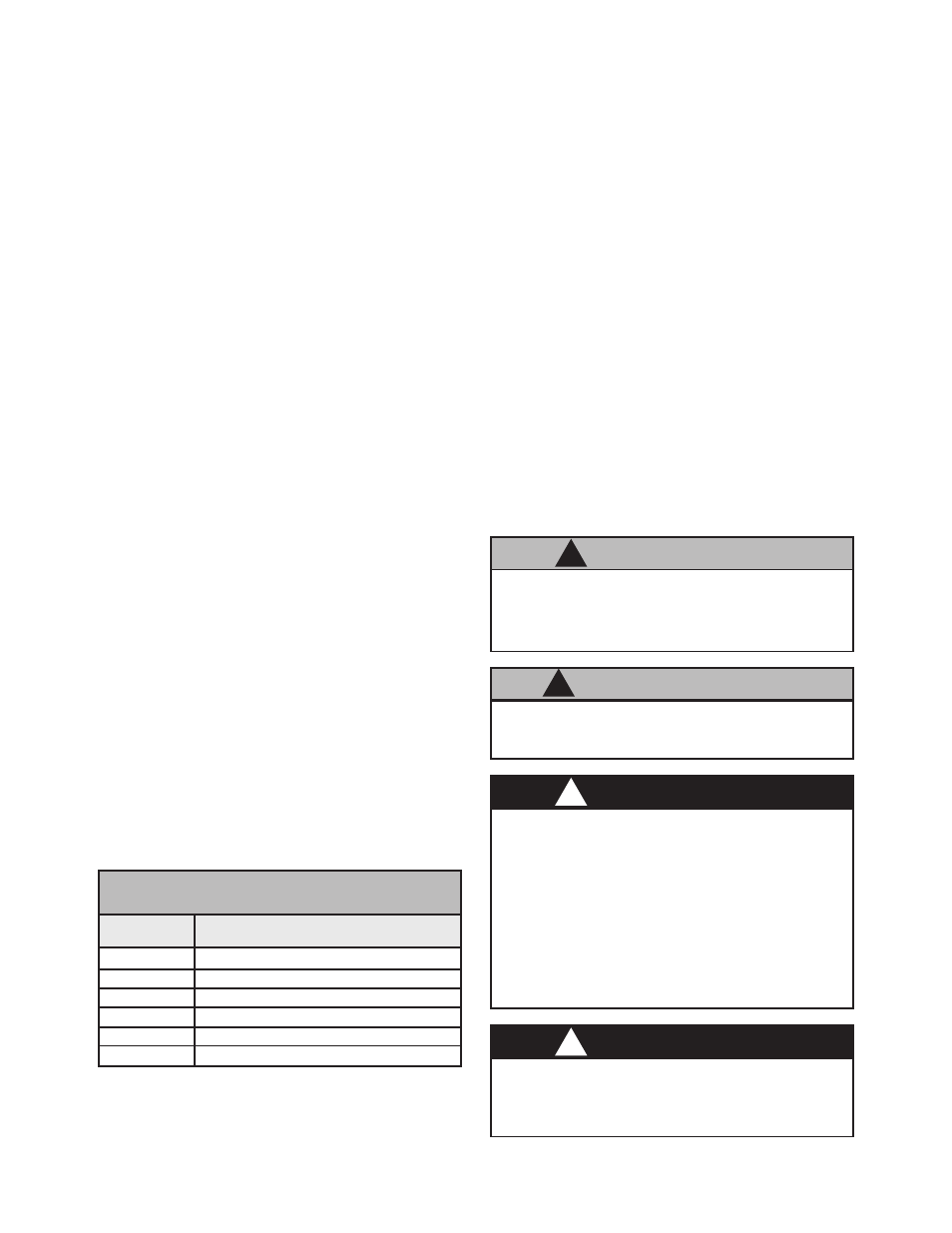
>
Do not exceed 100' combined length of the
low voltage cables.
C A U T I O N
!
79107-00
ABB Robots
78983-00
Fanuc P155, 145 Robots
79131-00
Fanuc P200 Robot
A10847-00
Adapter (Kawasaki-KE610L)
A10848-00
Adapter (Motoman-PX2850)
A10849-00
Adapter (Motoman-PX2900)
Part # Description
TABLE 1 - SPACER PLATES
>
Leave 12-24 inches of extra length on all
lines to prevent extreme tension being applied
to these lines during robot movement.
C A U T I O N
!
>
Install and route the hoses and cable so
that they are
NOT exposed to temperatures
in excess of 120
°
F. Ensure that all hose and
cable bends are
NOT LESS THAN a 6 inch
(15cm) radius and are not subjected to more
than 360
°
of torsional twist. Failure to comply
with these parameters could cause equipment
malfunctions that might create
HAZARDOUS
CONDITIONS!
W A R N I N G
!
>
If a non-explosion proof junction box/ter-
minal strip is used, it must be located outside
the hazardous area.
W A R N I N G
!
For installations utilizing the LECU5004-XX Micro-
Pak Power Supply, connect the low voltage cable
(79008-XX) from the robot manifold assembly to
the LECU5004-XX MicroPak Controller or junction
box. If connecting to a junction box, use a junction
cable (77062-XX) to make the connection from
the junction box to the LECU5004-XX MicroPak.
Make connections as shown in Figure 4.
For installations utilizing the A10406-XX Evolver
MicroPak Power Supply, connect the low voltage
cable (A11353-XX or A11356-XX) from the robot
manifold assembly or junction box to the receptacle
on the rear of the A10406-XX power supply. To
maintain FM Approval, this cable must be secured
to the stress relief bar on the rear of the power
supply. (See "A10406-XX Evolver
MicroPak Power Supply" manual for further in-
formation on connecting the low voltage cable.)
Evolver Solventborne Robotic Atomizers - Installation
17
Ransburg
AA-03-02.12