Appendix vii: setpoint outputs vs – Fairbanks H90-5200-A Digital Instrument User Manual
Page 51
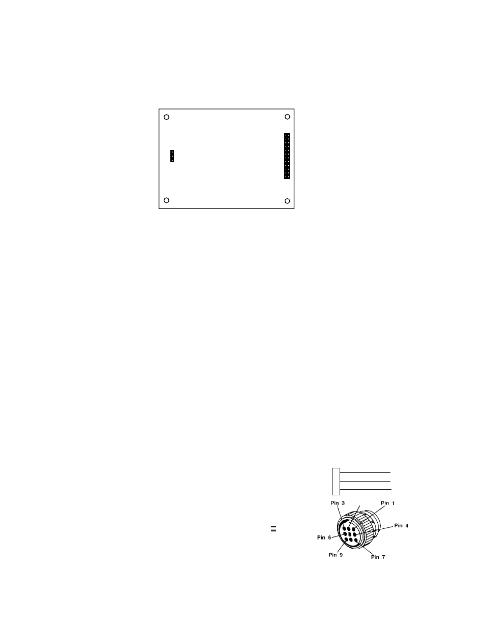
Accessory 148
SMART 4-20mA analog output board used to output to a chart recorder or control
system.
Four weld-studs are provided for mounting the accessory board.
To install the accessory:
1. Unplug the AC power cord from its outlet.
2. Remove the four bolts holding the front panel to the instrument.
3. Lift the instrument front panel and carefully remove all cables from the main PC
Board. Set the front panel and set it aside.
4. Remove the hole plug from the accessory port on the back of the instrument.
5. Install the 9 pin accessory connector in the accessory port.
6. Install the four hex spacers on the four weld-studs in the bottom of the instrument.
7. Place the accessory PC Board on the weld-studs. The 24 pin connector should be
toward the center of the instrument.
8. Install the four nuts on top of the weld-studs to hold the PC Board in place.
9. Connect the 24 pin ribbon cable from J1 on the accessory PC Board to J4 on the
main PC Board.
NOTE: Pin I on the cable must go to pin 1 on the accessory board and on the
instrument or damage may result. Make sure the cable exits towards the center
of the main PCB.
10. Connect the Accessory output cable from the 9
pin connector to J3 on the 4-20 Analog
Accessory.
11. Re-connect all of the cables to the main PC
Board.
12. Apply power and calibrate the 4-20mA output to
verify proper operation.
13. Re-install the front panel on the instrument.
APPENDIX VII: SETPOINT OUTPUTS VS.
50515
51
Issue #2 4/04
J1
J3
SMART 4-20mA ASSY
2429
2433
Pin 2
(9-Pin AMP)
1
2
3
+ Output
- Output(GND)
Shield
▲
▲
▲
To
Customer’s
Equipment
9-Pin Connector