Specifications - axtreme boom, Mechanical remote cable controled valve (standard), Control valve – Alamo Axtreme 02984405 User Manual
Page 18: Valve ports, Figure 1
© 2006
Alamo Industrial
Section 2 - 4
Axtreme Boom - Asy Man (07/06)
5.
Control Valve:
5 Spool used with Rotary Heads w/ Door
Valve Type................................................................................Open Center 5 Spool
Valve Control (Manual Standard)................................................. Remote Cable Control
Valve Control (Electonic Joystick Optional).................................. Joystick Electronic Control
Pressure (Maximum)................................................................. 3500 PSI
Flow (Maximum)....................................................................... 20 GPM
Main Relief............................................................................... Direct Acting: 3000 PSI: Adjustable
FilterType................................................................................. Return Side
Filter Size.................................................................................10 Micron
Bushings.................................................................................. Greasable Steel
6.
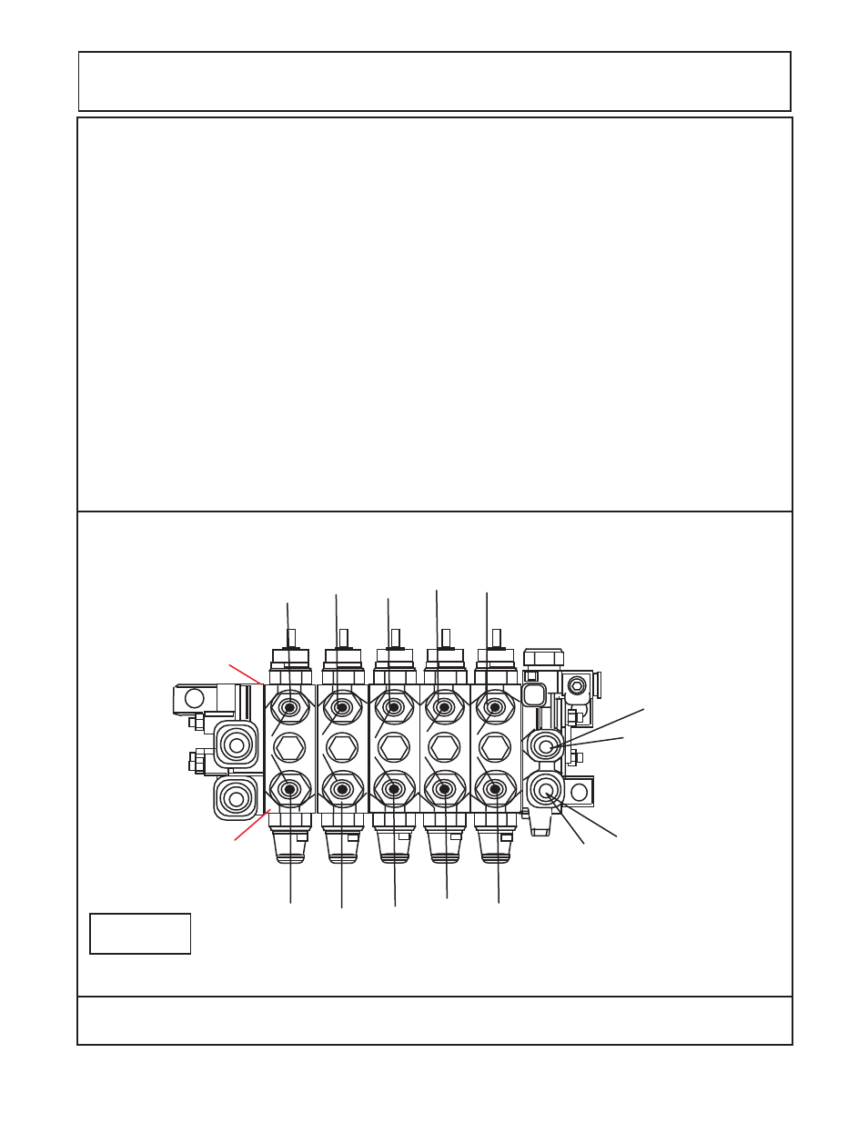
Valve Ports:
( See Figure 1 & 2)
"A" Port...........Valve Ports designated as "A" Ports connect to the Rod End of the Swing and Lift Cyl, to the
Barrel End of the Dipper Cyl, to the Barrel End of Tilt Cyl and to Barrel End of the Door Cyl.
"B" Port......... Valve Ports designated as "B" Ports connect to the Barrel End of Swing and Lift Cyl, to the
Rod End of the Dipper Cyl, to the Rod End of the Tilt Cyl and to the Rod End of the Door Cyl.
SPECIFICATIONS - AXTREME BOOM
Door
(Y
ellow /
White)
Tilt
(Red / White)
Tilt
(Red)
Dipper
(Blue / White)
Dipper
(Blue)
Lift
(Orange / White)
Lift
(Orange)
Swing
(Green / White)
Swing
(Green)
Pressure Supply (Port P1)
Return (Port T2)
1234567
1234567
1234567
12345678
12345678
12345678
1234567
1234567
1234567
1234567
12345678
12345678
12345678
12345678
12345678
12345678
12345678
12345678
123
123
123
123
123
123
123
123
123
123
123
123
1
1
12
12
1
1
1
1
12
12
Door
(Y
ellow)
1
2
3
4
1
2
2
A
B
A
A
A
A
B
B
B
B
Mechanical
Remote Cable
Controled Valve
(Standard)
Figure 1
"A" Port Side
"B" Port Side
Note:
Hose Colored Bands, Bands
with stripes go to Cylinder Base. Solid
color bands go to Cylinder rod end.