A" base, Figure 2: leveling the base, Rotating platform (rotated 90˚ as shown) – PASCO ME-8950A COMPLETE ROTATIONAL SYSTEM User Manual
Page 9: Rotating platform, Adjust this foot first, Leveling feet, 300g square mass, Then adjust this foot, Thumbscrew, Photogate head (optional)
012-05293F
Complete Rotational System
5
"A" base
Photogate Head
(optional)
thumbscrew
photogate
mount rod
10-spoke pulley
on vertical shaft
0
10
1
2
3
4
5
6
7
8
9
20
11
12
13
14
15
16
17
18
19
21
22
24
10
9
8
7
6
5
4
3
2
1
20
19
18
17
16
15
14
13
12
11
24
23
22
21
0
10
1
2
3
4
5
6
7
8
9
20
11
12
13
14
15
16
17
18
19
21
22
24
10
9
8
7
6
5
4
3
2
1
20
19
18
17
16
15
14
13
12
11
24
23
22
21
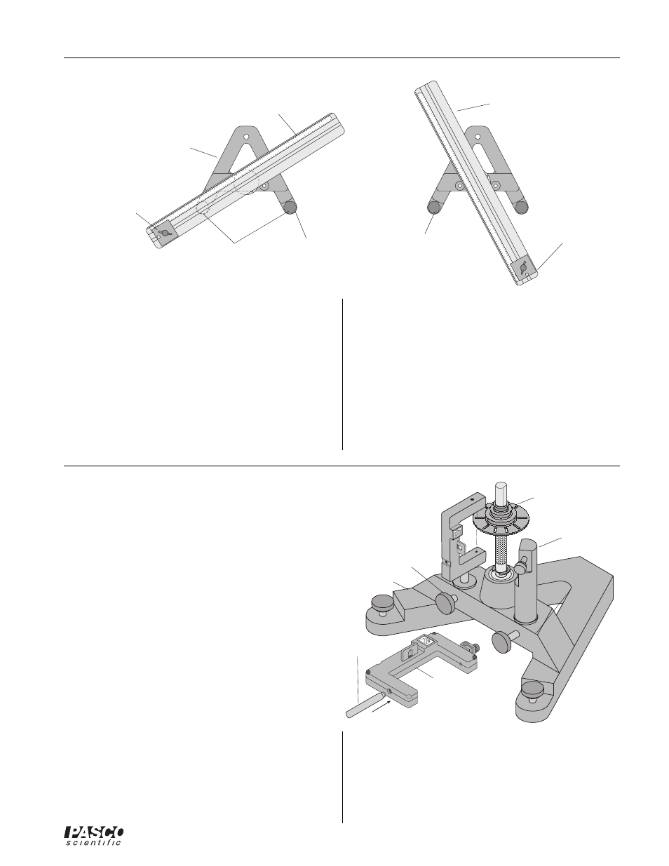
Figure 2: Leveling the Base
rotating platform
(rotated 90° as shown)
rotating plat-
form
Make sure that the Photogate Head does not rub against
the 10 spoke pulley or any other part of the apparatus.
5. Connect the cable to the Photogate Head and a PASCO
interface.
"A" base
adjust this foot
first
leveling feet
300g square
mass
300g square
mass
then adjust this
foot
Using an Optional Photogate Head
The optional Photogate Head (ME-9498A) can be
mounted to the Rotating Platform in two ways:
• Photogate Mount Rod can be used to mount the
Photogate Head directly to the base as shown in
Figure 3.
• Accessory Mounting Rod can to be used to mount
a Pulley Mounting rod and a Super Pulley along
with the Photogate Head to the base in order to run
a string over the Super Pulley. See Figure 4.
To Mount the Photogate Head Only:
1. Mount the Photogate Head on the threaded end of the
photogate mount rod.
2. Remove the swivel clamp from the top of the Photo-
gate Head.
3. Slide the non-threaded end of the photogate mount
rod into a hole in the A-base and clamp it in place with
the thumbscrew.
4. Adjust the Photogate Head so that its infrared beam
can be interrupted by the 10 spoke pulley on the
vertical shaft as the shaft turns.
accessory
mounting rod
Figure 3: Using the Photogate Mount Rod With the
Photogate Head
Leveling the Base
Some experiments (such as the Centripetal Force exper-
iments) require the apparatus to be extremely level. If the
track is not level, the uneven performance will affect the
results. To level the base, perform the following steps:
1. Purposely make the apparatus unbalanced by attach-
ing the 300 g square mass onto either end of the
aluminum track. Tighten the screw so the mass will
not slide. If the hooked mass is hanging from the side
post in the centripetal force accessory, place the
square mass on the same side.
2. Adjust the leveling screw on one of the legs of the
base until the end of the track with the square mass is
aligned over the leveling screw on the other leg of the
base. See Figure 2.
3. Rotate the track 90 degrees so it is parallel to one side
of the “A” and adjust the other leveling screw until
the track will stay in this position.
4. The track is now level and it should remain at rest
regardless of its orientation.