A"-base, Experiment 7: conservation of angular momentum, Rotational disk (indentation up) – PASCO ME-8950A COMPLETE ROTATIONAL SYSTEM User Manual
Page 45: Figure 7.1: assembly for dropping ring onto disk, Purpose, Theory, Setup
012-05293F
Complete Rotational System
41
Experiment 7: Conservation of Angular
Momentum
EQUIPMENT REQUIRED
- DataStudio Program
- PASCO Interface
- Rotational Inertia Accessory (ME-8953)
- Balance
- Rotating Platform (ME-8951)
- Photogate/Pulley System
Purpose
A non-rotating ring is dropped onto a rotating disk and the final angular speed of the system
is compared with the value predicted using conservation of angular momentum.
Theory
When the ring is dropped onto the rotating disk, there is no net torque on the system since the
torque on the ring is equal and opposite to the torque on the disk. Therefore, there is no change
in angular momentum. Angular momentum is conserved
.
where I
i
is the initial rotational inertia and
ω
i
is the initial angular speed. The initial rotational
inertia is that of a disk
and the final rotational inertia of the combined disk and ring is
So the final rotational speed is given by
Setup
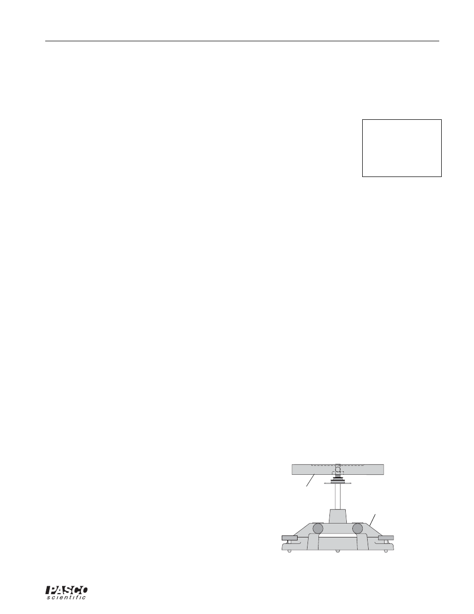
1. Level the apparatus using the square mass on the track.
2. Assemble the Rotational Inertia Accessory as shown in Figure
7.1. The side of the disk with the indentation for the ring should
be up.
3. Mount the Photogate on the metal rod on the base and position it
so it straddles the holes in the pulley on the center rotating shaft.
4. Start the DataStudio program. Select ’Smart Pulley (Rota-
tional)’ as the sensor.
5. Set up a Graph display of Velocity (rad/s) versus Time (s).
L
I
i
ω
i
I
f
ω
f
=
=
I
i
1
2
--- M
1
R
2
=
I
f
1
2
--- M
1
R
2
1
2
---M
2
r
1
2
r
2
2
+
(
)
+
=
ω
f
M
1
R
2
M
1
R
2
M
2
r
1
2
r
2
2
+
(
)
+
-------------------------------------------------
ω
i
=
Note: If you are
using a PASPORT
interface, you will
also need a Digital
Adapter (PS-2159)
"A"-base
Rotational Disk
(indentation up)
Figure 7.1: Assembly for Dropping
Ring onto Disk