Figure 3.1: centripetal force apparatus, Rotating platform, Hanging mass – PASCO ME-8950A COMPLETE ROTATIONAL SYSTEM User Manual
Page 24: Center post assembly, Side post assembly, Clamp-on pulley, A" base, String, Table 3.1: varying the radius
Complete Rotational System
012-05293F
20
2. Attach the clamp-on pulley to the end of the track nearer to the hanging object. Attach a string to
the hanging object and hang a known mass over the clamp-on pulley. Record this mass in Table
3.1. This establishes the constant centripetal force.
3. Select a radius by aligning the line on the side post with any desired position on the measuring
tape. While pressing down on the side post to assure that it is vertical, tighten the thumb screw on
the side post to secure its position. Record this radius in Table 3.1.
4. The object on the side bracket must hang vertically: On the center post, adjust the spring bracket
vertically until the string from which the object hangs on the side post is aligned with the vertical
line on the side post.
5. Align the indicator bracket on the center post with the orange indicator.
6. Remove the mass that is hanging over the pulley and remove the pulley.
7. Rotate the apparatus by hand, increasing the speed until the orange indicator is centered in the
indicator bracket on the center post. This indicates that the string supporting the hanging object is
once again vertical and thus the hanging object is at
the desired radius.
8. Maintaining this speed, use a stopwatch to time
ten revolutions. Divide the time by ten and
record the period in Table 3.1.
9. Move the side post to a new radius and repeat
the procedure. Do this for a total of five radii.
Analysis
1. The weight of the mass hanging over the pulley
is equal to the centripetal force applied by the
spring. Calculate this force by multiplying the
mass hung over the pulley by “g” and record this
force at the top of Table 3.2.
2. Calculate the square of the period for each trial
and record this in Table 3.1.
3. Plot the radius versus the square of the period. This will give a straight line since:
4. Draw the best-fit line through the data points and measure the slope of the line. Record the slope
in Table 3.1.
r
F
4
π
2
m
-------------
⎝
⎠
⎛
⎞ T
2
=
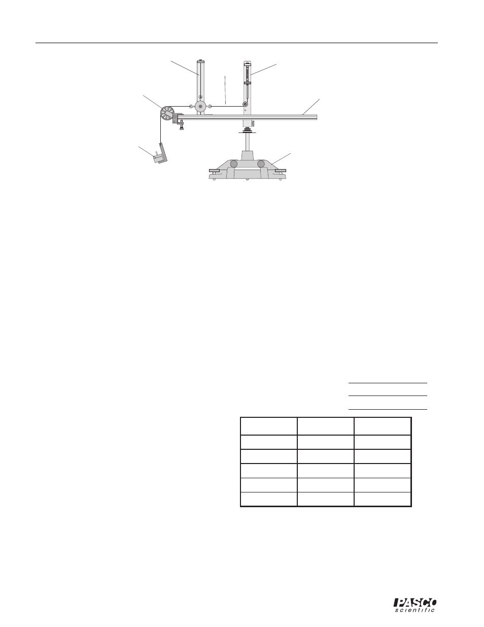
string
center post
assembly
side post
assembly
Figure 3.1: Centripetal Force Apparatus
Radius
Period (T)
T
2
Mass of the object =
Mass hanging over the pulley =
Slope from graph =
rotating
platform
hanging
mass
clamp-on
pulley
"A" base
Table 3.1: Varying the Radius