Part ii: conservation of angular momentum, Level the rotating platform, Rubber band – PASCO ME-8950A COMPLETE ROTATIONAL SYSTEM User Manual
Page 16: Catcher, Side view of rotating platform, End view of rotating platform, Tab of "catcher" against platform, Table 1.2 initial speed using photogates, Figure 1.4: attaching the catcher to the track, Table 1.3 angular speed
Complete Rotational System
012-05293F
12
5. The distance between the Photogates is 10 cm. Calculate the initial speed and record it in Table
1.2 and Table 1.4.
Part II: Conservation of Angular Momentum
Setup
1. Find the mass of the ball and record it in Table 1.3.
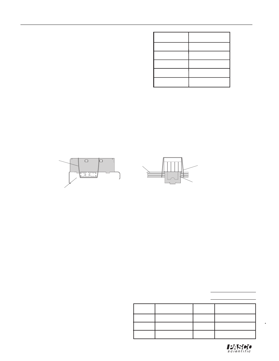
2. Attach the ball catcher to the track using a rubber band as shown in Figure 1.4.
3. With the Projectile Launcher mounted as it was in Part I, aim the launcher directly down the mid-
dle of the ball catcher using the sights inside the projectile launcher. Clamp the launcher to the
table.
4. Attach the Photogate Head to the base. Connect the Photogate Head to a computer and run the
DataStudio program.
5. Set up the program so that it measures and displays angular speed.
Procedure
1. Level the rotating platform.
2. Load the Launcher with the steel ball on the long range setting.
3. Make sure the rotating platform is at rest and fire the ball into the catcher.
Record the angular speed of the platform in Table
1.3. Repeat for a total of five shots.
4. Measure the distance from the axis of rotation to
the ball in the catcher and record in Table 1.3.
side view of
rotating platform
"catcher"
end view of
rotating platform
rubber band
rubber band
3
Time
Trial Number
Average Time
Initial Velocity
1
2
tab of "catcher"
against platform
Table 1.2 Initial Speed Using Photogates
Figure 1.4: Attaching the Catcher to the Track
1
2
3
4
5
Avg.
Mass of ball =
Distance from axis of rotation, R =
Trial
Trial
Angular Speed
Angular Speed
Table 1.3 Angular Speed