PASCO WA-9611_13 SONOMETER User Manual
Page 9
5
012-03489E
Sonometer
➁
Connect the BNC plug on the Sonometer Detector
Coil to the BNC adapter that is included with the
Driver/Detector Coils. Connect the banana plugs of a
CI-6503 Voltage Sensor to the BNC adapter. Connect
the DIN plug of the Voltage Sensor to channel A of
the interface.
➂
Start the Science Workshop program. In the Experi-
ment Setup window, click-and-drag the analog sensor
plug icon to channel C. Select “Power Amplifier”
from the list of sensors. Set the Signal Generator out-
put to a 3-5 V sine wave. Click on “Auto ON/OFF”
(so the output signal will begin when you start your
measurements) and switch on the power amplifier.
➃
In the Experiment Setup window, click-and-drag the
analog sensor plug icon to channel A. Select “Sound
Sensor” from the list of sensors. Click-and-drag a
Scope display to the Output channel icon in the Setup
window.
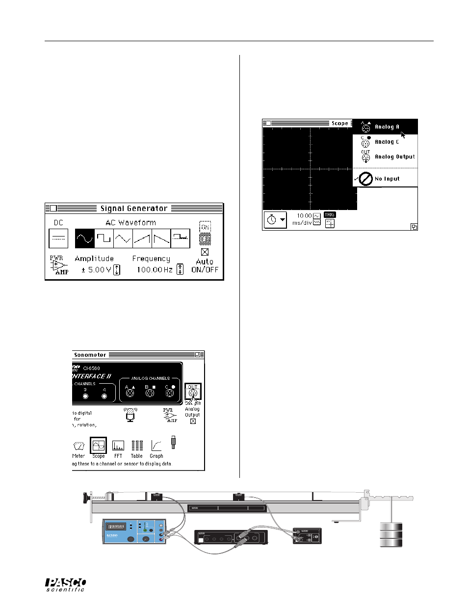
➄
In the Scope, use the input menu for the second chan-
nel to select “Analog A” so the Scope will show both
the driving signal and the detected motion of the wire.
Set the sensitivity for the Analog A channel to about
0.005 v/div.
For frequency analysis, select “New FFT” from the Display
menu. Click on “MON” in the Setup window (or command-
M on the keyboard) when you are ready to begin.
Using a Function Generator with the Series 6500
Computer Interface:
The MS-DOS and Windows™ versions of the Data
Monitor program allow you to do frequency analysis
(Fast Fourier Transform or FFT) of the standing waves.
This can be used for an in-depth analysis of the harmon-
ics present in a standing wave, analysis of noise, or obser-
vation of multiple simultaneous resonances.
➀
Connect the BNC plug on the Sonometer Detector
Coil to the BNC jack on the CI-6508 Input Adapter
Box, and the DIN plug on the Adapter Box to channel
A of the Series-6500. Turn the amplification select
switch on the CI-6508 to 100X.
➁
If you have a CI-6503 Voltage Sensor, use it to link
the function generator to channel B of the CI-6500
interface. (This step is optional; it allows you to use
the function generator for triggering, with slightly im-
proved results.) See Figure 5.2.
WA-9611
SONOMETER
KEEP WEIGHTS AS NEAR TO FLOOR
AS POSSIBLE IN THE EVENT THE
SONOMETER WIRE SHOULD BREAK
CAUTION!
1.75 kg MAXIMUM
LOAD ON LEVER
T T
L
H I
Ω
G
N D
L O
Ω
M I
N
R A
N G E
A D J U
S T
M
A X
O U T P
U T
F R E Q U E N
C Y
A M P L I T U
D E
P I - 9 5 8 7 B
D I G I TA L F U N C T I O N
G E N E R AT O R -
A M P L I F I E R
H E
R T Z
WAV E F O
R M
I N P
U T
G
N D
E X T E R N
A L
1
2
3
4
DIGITAL CHANNELS
ANALOG CHANNELS
A
▲
B
■
C
●
ON
GAIN = 1,10,100
ISOLATED
GAIN = 1
ISOLATED
GAIN = 1
REF TO GND
INTERFACE
SYSTEM
PASCO
6500
SERIES
CI-6510
SIGNAL INTERFACE
FOR USE WITH PASCO SERIES 6500 SENSORS
GAIN SELECT
NOTE: SWITCH
FUNTIONS ONLY WHEN
ADAPTOR IS
CONNECTED TO INPUT
MARKED ▲ ON THE
SIGNAL INTERFACE
X 100
X 10
X 1
INTERFACE
SYSTEM
PASCO
6500
SERIES
ANALOG INPUT
(
±
10V MAX)
INPUT ADAPTOR
FOR USE WITH PASCO SERIES 6500 INTERFACES
Model CI-6508
DRIVER
WA-9613
DETECTOR
WA-9613
Figure 5.2 Using a Function Generator and the Series 6500
CI-6508
CI-6500
PI-4587C Function Generator