PASCO WA-9611_13 SONOMETER User Manual
Page 8
4
Sonometer
012-03489E
➂
Start the Power Amplifier program and set the output
to a 3-5 V sine wave; then turn on the power ampli-
fier. Show channel A and channel C on the screen, so
you can see both the driving force and the resultant
motion of the wire.
➤ NOTE: The Power Amplifier program does not
have a frequency analysis feature (Fast Fourier
Transform or FFT).
Using the Power Amplifier with a CI-6550 or CI-6565
Computer Interface:
The Science Workshop program that comes with the CI-
6550 or CI-6565 interface allows you to do frequency
analysis (Fast Fourier Transform, or FFT) of the standing
waves. This can be used for an in-depth analysis of the
harmonics present in a standing wave, analysis of noise,
or observation of multiple simultaneous resonances.
➀
Connect the Power Amplifier DIN plug to channel C
of the interface. Connect the Sonometer Driver Coil to
the output of the Power Amplifier.
➤ CAUTION: Do not turn on the power amplifier
until you have set the output amplitude from within
the program.
Table 1
Sonometer and Driver/Detector Coils with a PASCO
Computer Interface
There are several ways to use a PASCO Computer Inter-
face with the sonometer. The method you use depends on
the kind of computer, the interface (e.g., CI-6500, CI-
6550, etc.), the device to control the coil, and whether you
wish to do frequency analysis (Fast Fourier Transform or
FFT) of the standing waves. See Table 1.
Using the Power Amplifier with a Series 6500
Computer Interface:
➀
Connect the Power Amplifier DIN plug to channel C
of the interface. Connect the Sonometer Driver Coil to
the output of the Power Amplifier.
➤ CAUTION: Do not turn on the power amplifier
until you have set the output amplitude from within
the program.
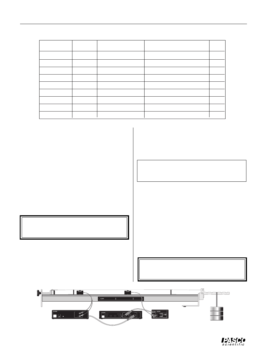
➁
Connect the BNC plug on the Sonometer Detector
Coil to the BNC jack on the CI-6508 Input Adapter
Box, and the DIN plug on the Adapter Box to channel
A of the interface. Turn the amplification select switch
on the CI-6508 to 100X. (See Figure 5.1.)
Computer
Interface
Device to drive coil
Software
FFT?
Apple II
AI-6501
Power Amplifier
Power Amplifier (Apple II)
no
Apple II
AI-6501
function generator
Data Monitor (Apple II)
no
DOS - PC
CI-6500
Power Amplifier
Power Amplifier (MS-DOS)
no
DOS - PC
CI-6500
function generator
Data Monitor (MS-DOS)
yes
Macintosh
CI-6550
Power Amplifier
Science Workshop (Mac)
yes
Macintosh
CI-6550
function generator
Science Workshop (Mac)
yes
Windows - PC CI-6565
Power Amplifier
Science Workshop (Windows)
yes
Windows - PC CI-6565
function generator
Science Workshop (Windows)
yes
Windows - PC CI-6500
function generator
Data Monitor (Windows)
yes
WA-9611
SONOMETER
KEEP WEIGHTS AS NEAR TO FLOOR
AS POSSIBLE IN THE EVENT THE
SONOMETER WIRE SHOULD BREAK
CAUTION!
1.75 kg MAXIMUM
LOAD ON LEVER
1
2
3
4
DIGITAL CHANNELS
ANALOG CHANNELS
A
▲
B
■
C
●
ON
GAIN = 1,10,100
ISOLATED
GAIN = 1
ISOLATED
GAIN = 1
REF TO GND
INTERFACE
SYSTEM
PASCO
6500
SERIES
CI-6510
SIGNAL INTERFACE
FOR USE WITH PASCO SERIES 6500 SENSORS
CI-6502
POWER AMPLIFIER
FOR USE WITH PASCO SERIES 6500 INTERFACES
ON
+
INTERFACE
SYSTEM
PASCO
6500
SERIES
SIGNAL OUTPUT
0 to
±
10 V
1 A MAX
CAUTION!
WHEN LIGHT IS ON
WAVEFORM IS DISTORTED.
DECREASE AMPLITUDE!
GAIN SELECT
NOTE: SWITCH
FUNTIONS ONLY WHEN
ADAPTOR IS
CONNECTED TO INPUT
MARKED ▲ ON THE
SIGNAL INTERFACE
X 100
X 10
X 1
INTERFACE
SYSTEM
PASCO
6500
SERIES
ANALOG INPUT
(
±
10V MAX)
INPUT ADAPTOR
FOR USE WITH PASCO SERIES 6500 INTERFACES
Model CI-6508
DRIVER
WA-9613
DETECTOR
WA-9613
Figure 5.1 Using the Power Amplifier and Series 6500 Interface
Power Amplifier
Adapter Box
Interface