Slide the aluminum cylinder out of the slot, Figure 5 using the driver and detector coils, Manual auto – PASCO WA-9611_13 SONOMETER User Manual
Page 7: Driver coil detector coil
3
012-03489E
Sonometer
➤NOTE: At some lab stations, you may want the
tensioning lever to hang over the left end of the
table instead of the right (see Figure 4). In this case,
you can switch the end plates so that, when per-
forming the experiment, the metric scale will still
be right side up. To switch the endplates:
➀
Loosen the string adjustment screw and remove
the string.
➁
Unscrew the two screws that hold each end plate
onto the sonometer and remove the end plates.
➂
Slide the aluminum cylinder out of the slot.
➃
Slide the cylinder into the slot on the other end
of the sonometer, then switch the end plates.
Using the Sonometer and the WA-9613
Driver/Detector Coils:
Sonometer and Driver/Detector Coils with a function
generator and oscilloscope:
➀
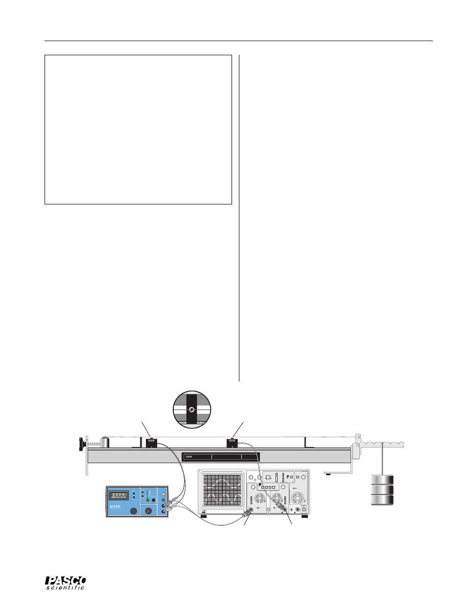
Connect the Driver and Detector Coils to the function
generator and oscilloscope as shown in the diagram.
Connect the driver coil directly to the output of the
PASCO PI-9587B Digital Function Generator. Con-
nect the detector coil directly to channel two of an os-
cilloscope that has a BNC connector. You can use ba-
nana plug patch cords and a BNC-to-banana plug
adapter to connect the output of the function generator
to channel one of an oscilloscope that has a BNC con-
nector. (If you are using a single trace oscilloscope,
connect only the detector coil to the oscilloscope.)
➁
Position the driver coil approximately 5 cm from one
of the bridges.
Depending on the wave pattern you are trying to pro-
duce, you might want to place the driver at some other
position. It will drive the string best if it is placed at an
antinode of the wave pattern. However, if you place it
near one of the bridges, it will work reasonably well
for most frequencies.
➂
Position the detector midway between the bridges ini-
tially, though for some patterns you may want to repo-
sition it to best pick up the signal. As with the driver
coil, it works best when positioned near an antinode of
the wave pattern.
➃
Set the gain on channel-one of the oscilloscope to 5
mV/cm. Adjust the oscilloscope so it triggers on the
signal from the function generator.
➄
Set the function generator to produce a sine wave. Set
the frequency to a value between 100 and 200 Hz. Ad-
just the amplitude to about 5 V (approximately half of
maximum). Slowly vary the frequency of the function
generator output. When you reach a resonant fre-
quency, you should see the motion of the string and
the sound produced by the vibrating string should be a
maximum. The wave pattern shown on the oscillo-
scope should become a clean sine wave. If you can’t
see or hear the string, raise the amplitude of the func-
tion generator output slightly and try again.
Figure 5 Using the Driver and Detector Coils
Driver coil
Detector coil
WA-9611
SONOMETER
KEEP WEIGHTS AS NEAR TO FLOOR
AS POSSIBLE IN THE EVENT THE
SONOMETER WIRE SHOULD BREAK
CAUTION!
1.75 kg MAXIMUM
LOAD ON LEVER
BK PRECISION
200 Mhz OSCILLISCOPE
MODEL
2120
INTENSITY
FOCUS
TRACE NOTATION
TRIG LEVEL
COUPLE
SOURCE
SLOPE
λ
- Y
TIME/DI
V
X-POS
VAR
VAR
VAR SWEEP
CAL
CAL
mV
V
CH 1
VOLTZ/DIV
CH 2
VOLTZ/DIV
CAL
mV
V
VERTICAL MODE
PULL XS
PULL XS
CH 2
∞
CH 1
∞
AC
DC
AC
DC
AC
CH1
CH2
ALT
EXT
POS
POS
NORM
EXT
CH1
CH2
NORM
EXT
CH1
CH2
MANUAL AUTO
T X-
Y
T X-
Y
LINE
CAL
EXT CH4
POWER
200V
MAX
400V
MAX
400V
MAX
-
+
+
-
T T
L
H I
Ω
G
N D
L O
Ω
M I
N
R A
N G E
A D J U
S T
M
A X
O U T P
U T
F R E Q U E N
C Y
A M P L I T U
D E
P I - 9 5 8 7 B
D I G I TA L F U N C T I O N
G E N E R AT O R -
A M P L I F I E R
H E
R T Z
WAV E F O
R M
I N P
U T
G
N D
E X T E R N
A L
DETECTOR
WA-9613
DRIVER
WA-9613
Oscilloscope
Channel 1 (trigger)
Channel 2
Function generator