Flat beams, Attaching cords, Connectors – PASCO ME-6992B Advanced Structures Set User Manual
Page 8
®
A d v a n c e d S t r u c t u r e s S e t
A b o u t t h e C o m p o n e n t s
4
012-12719B
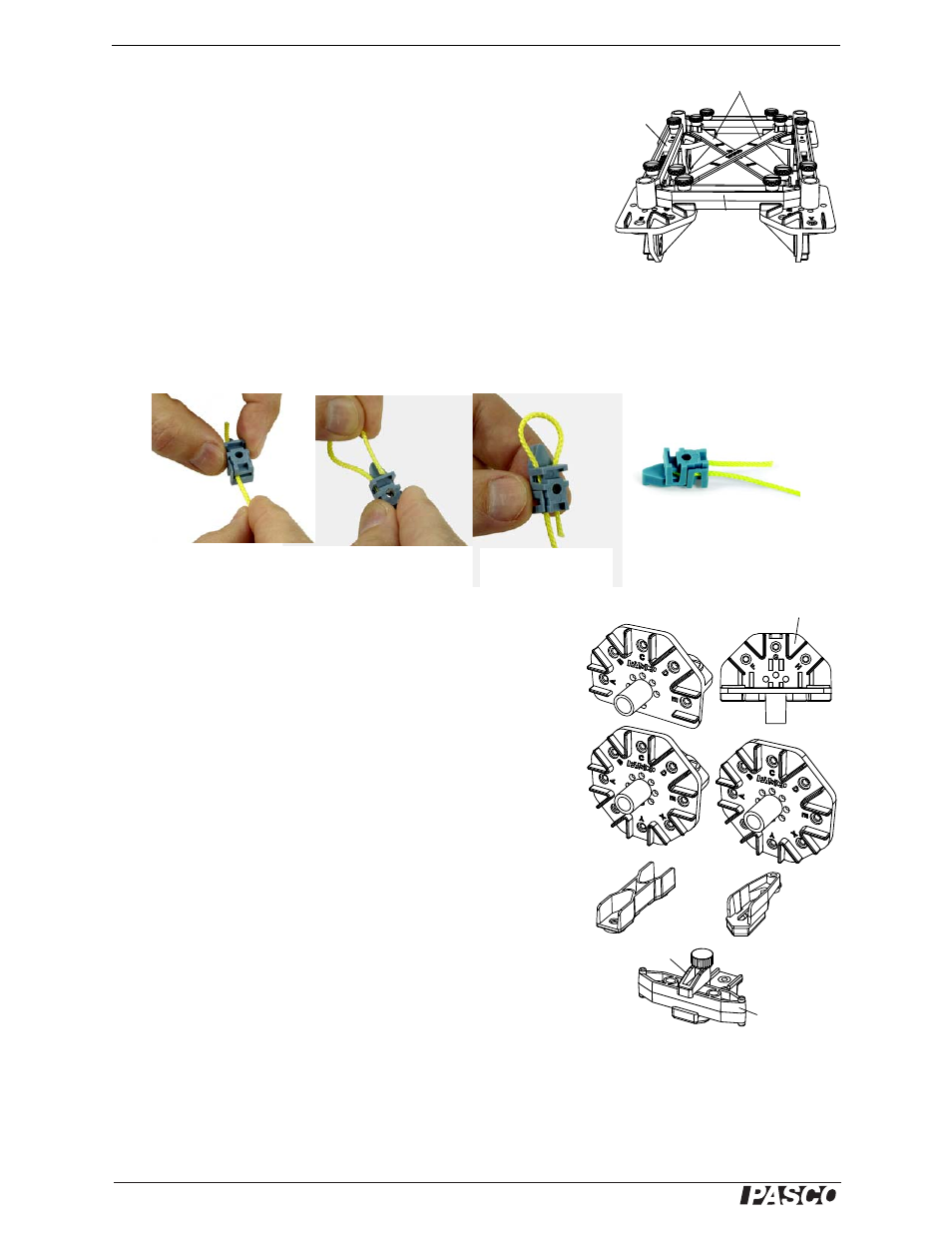
Flat Beams
Flat Beams are used for cross-bracing.
Attaching Cords
When attaching cords for lateral bracing or for suspension or cable-stayed
bridges, Cord Tensioning Clips are used to assist in adjusting the tension in
the cords.
The Cord Clip does not come apart. It is best to thread the cord through the
clip before the clip is installed on the bridge or structure. Prepare to thread
the cord by holding the top half of the clip as shown in Figure 4a so the two halves of the clip will separate, leav-
ing an opening through which the cord is threaded. The cord is inserted into the end opposite the pointed end of
the clip. The cord should be looped back through the clip as shown in Figure 4c. Then the Cord Clip can be used
in the structure, using the attachment screw to tighten the clip shut. To adjust the cord tension, loosen the screw
and pull on the cord to the desired tension and then tighten the screw.
Connectors
Half Round Connector: The half round connector has eight slots,
labeled A through H, for accepting beams.
Full Round Connector: The full round connector has eleven slots,
labeled A through H and X, Y, and Z, for attaching beams
Flat Connector: The flat connector has eight slots, labeled A through
E, and X, Y, and Z, for attaching beams.
Straight Connector: The straight connector can connect two beams to
make a longer beam.
Angle Connector: The angle connector can allow a beam to be con-
nected to a half round connector, full round connector, or flat connec-
tor at an angle different than zero, 45, or 90 degrees. The Angle
Connector also allows for a small adjustment of the length of the
beam.
Sliding Connector: The sliding connector allows one beam to be con-
nected to another beam at any position along the length of the second
beam. To use the sliding connector, loosen the thumbscrew and rotate
the top “jaw” to the side. Place the beam onto the lower part of the
connector, rotate the top “jaw” into place, and tighten the thumbscrew.
2 X 3 Flat Beams
Figure 3: Flat Beams
#3
#2
Figure 4a: Hold half of
the cord clip so the
two halves separate
Figure 4b: Loop the
cord back through the
cord clip
Figure 4c: The cord
goes around the
screw hole
Figure 4d: The cord clip is
ready to be attached to the
structure using a screw
Half Round
Full Round
Flat
Straight
Angle
Figure 5: Connectors
Sliding
I-Beam #1
“Jaw”
Top view