Forces on a boom: details – PASCO ME-6992B Advanced Structures Set User Manual
Page 16
®
A d v a n c e d S t r u c t u r e s S e t
F o r c e s o n a B o o m
12
012-12719B
Forces on a Boom: Details
Load Cells
The “Forces on a Boom” structure is shown with four Load Cells measuring the horizontal and vertical forces of
the axle on the base of the boom. The experiment can be performed using only two Load Cells on the base, both
on one side, but care must be given to ensure that the boom is centered and balanced side-to-side. The actual
force will be two times the measured value.
Suggestions
The triangular support structure for the upper pulley is constructed to allow the cord to be horizontal. By using
different components, students can change the height of the pulley and thus vary the angle of the cord. How does
that affect the measured forces?
The supporting cord is shown tied to a cross member near the end of the boom. What changes if the cord is
moved to the end of the boom or to a cross member closer to the base of the boom?
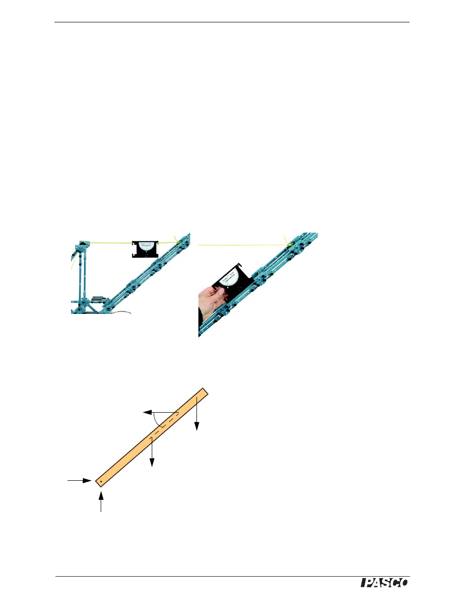
Angle Indicator
The ME-9495 Angle Indicator can be used both on the cord and on the boom itself.
Force Vector Diagram
The following diagram shows the various forces acting on the boom.
W
W
b
T
F
y
F
x