Example: bridge with load cells, Calibration of load cells, Properties of i-beams – PASCO ME-6992B Advanced Structures Set User Manual
Page 10: Simple triangles
®
A d v a n c e d S t r u c t u r e s S e t
P r o p e r t i e s o f I - b e a m s
6
012-12719B
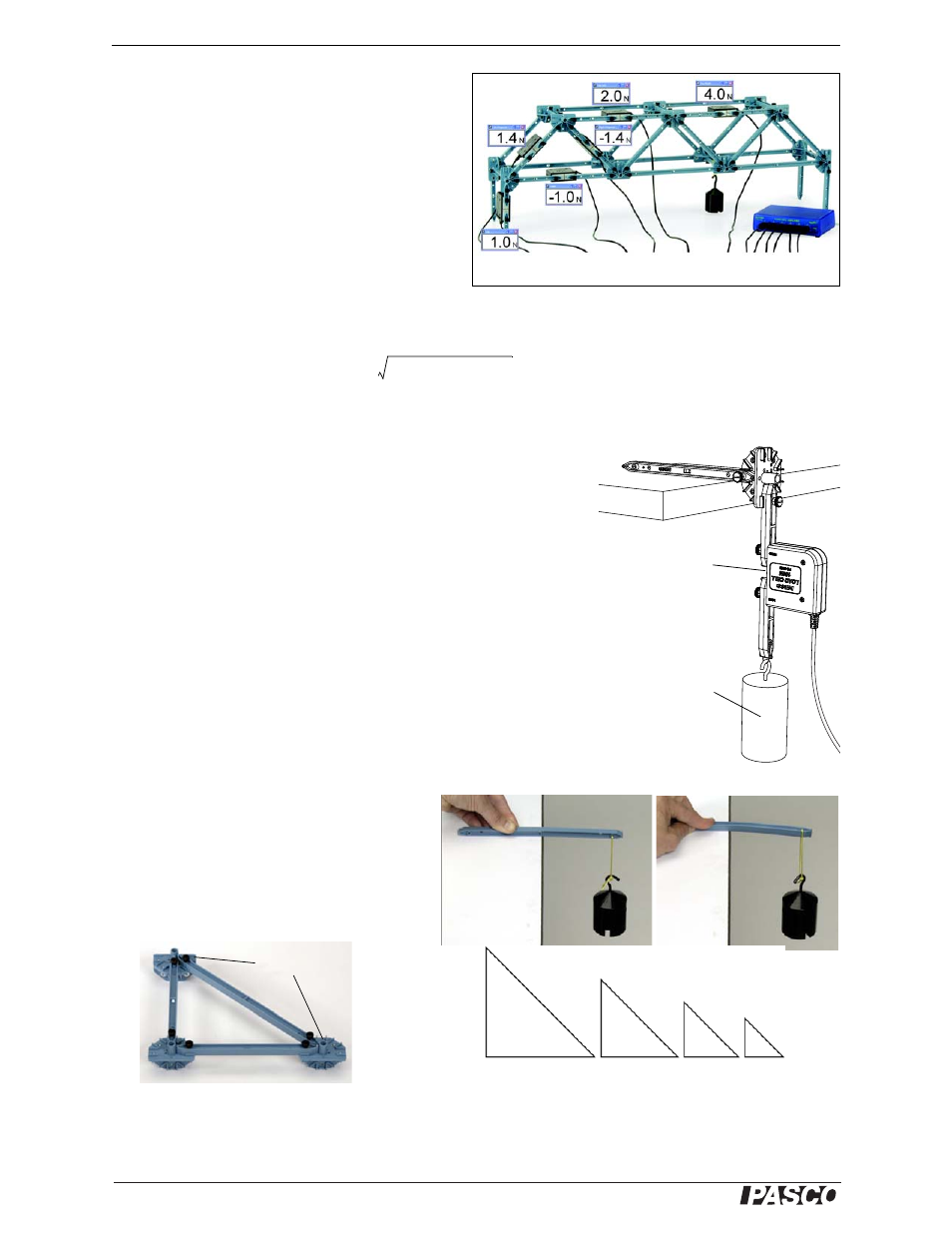
Example: Bridge with Load Cells
The bridge shown in Figure 9 incorporates six load
cells to measure the tension or compression in vari-
ous members. A hanging mass is used to apply load.
The mass is adjusted so that the compression in one
of the legs is 1.0 N. Compression is registered as a
positive value and tension as a negative value.
If the screws are loose, the theoretical analysis of
the bridge can be carried out by assuming that the
net force at each node is zero. Thus, the vertical
component of compression in the left-most diagonal member must be 1 N (to oppose the force applied by the
leg). The horizontal component must also be 1 N since the member is at a 45° angle. The predicted resultant
force is:
The actual measured force confirms the theory.
Calibration of Load Cells
Load cells are factory calibrated; however, you can re-calibrate them in
software or on the datalogger. Assemble the fixture shown in Figure 10
to support the load cell. See the documentation for your software or
datalogger for instructions.
When calibrating a load cell, it is necessary to apply a known load. Hold
or clamp the fixture at the edge of a table and hang a mass from it as
shown.
Note that the hanging mass applies tension to the load cell; therefore the
known force that you enter into the software or datalogger should be a
negative value. For example, if the mass is 1.0 kg, the applied force is
-9.8 N.
Properties of I-beams
Figure 11 shows the difference between the X
and Y bending moments of an I-beam.
Simple Triangles
Most structures are made of isosceles right tri-
angles as shown in Figure 12.
Figure 9: Bridge with Load Cells
1.0 N
2
1.0 N
2
+
1.4 N
=
Figure 10:
Calibration fixture
Load Cell
Mass
Figure 11: Bending an I-Beam
#4
#4
#5
#4
#3
#3
#3
#2
#2
#2
#1
#1
Figure 12: (Left) A triangle made from a #5 beam and two #4 beams. (Right) Combinations of beams to make triangles.
Half Round
connector