PASCO CI-6729 (1X) CONDUCTIVITY SENSOR User Manual
Page 9
5
012–06485B
Conductivity Sensor
electrodes can be placed closer together, reducing the length between them
and producing cell constants of 0.1 or 0.01. This will raise the conductance
reading by a factor of 10 to 100 to offset the low solution conductivity and
give a better signal to the conductivity meter. On the other hand, the sensing
electrodes can be placed farther apart to create cell constants of 10 or 100
for use in highly conductive solutions. Table 2 lists the optimum conductivity
range for cells with different cell constants.
Table 2. Optimum Conductivity Range For Cells
With Different Cell Constants
Cell Constant
Conductivity
0.01
0–20
µS/cm
0.1
0–200
µS/cm
1.0
0–2000
µS/cm
10.0
0–200,000 µS/cm
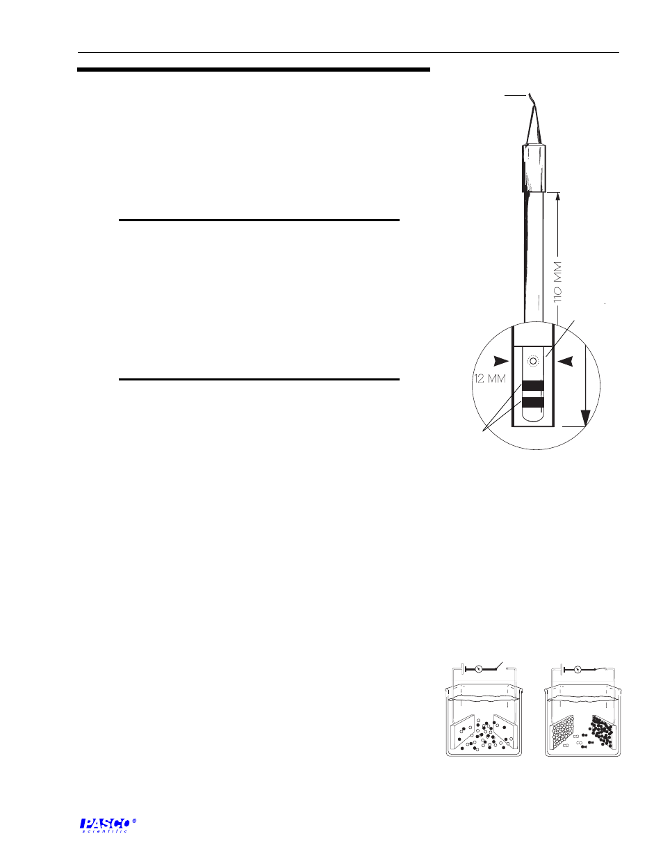
The conductivity electrode provided with the CI-6729 has a cell constant of
1.0 and is designed to achieve optimum performance over a range of 0 to
20,000 µS (Figure 2). This performance is achieved by using a cylindrical
cell geometry and platinized platinum conductors embedded on a glass rod.
For measurements of conductivity greater than 20,000 µS, the 10x electrode
should be used.
Conductivity Sensor Amplifier
The Conductivity Sensor amplifier has two distinct functions. First, it provides
a signal or voltage used to drive the conductivity electrode, and second, it
senses the electrical current the electrode passes when placed in the solution
to be tested.
If the voltage and current are known, then the resistance of the cell can be
determined. If the resistance of the cell is known, then the conductivity can
be determined by taking the inverse of the resistance and multiplying by the
conductivity cell constant. While it is instructional to know how the sensor
determines conductivity, Science Workshop handles the calculations and
reports conductivity for the 1x cell directly. If the 10x conductivity electrode
is used, the value reported by Science Workshop should be multiplied by ten.
When a potential is a applied to the conductivity cell, the ions in solution are
influenced by the charge on the cell’s electrodes and begin to migrate toward
the electrodes (Figure 3).
Figure 2
Schematic view of the cell for the
CI-6729 Conductivity Electrode.
E
-
+
E
Figure 3
Conductivity Cell in operation
glass rod
platinized
platinum
conductors
to amplifier box