Typical wiring: sp714 & sp717, Analog outputs, Voltage out – Liquid Controls SP2850 (MS-649) User Manual
Page 9: Current out
Sponsler, Inc.
Model SP2850-TC with MS649
Page 9
DOC#: MN-2850
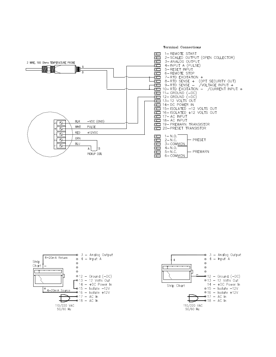
TYPICAL WIRING: SP714 & SP717
ANALOG OUTPUTS
The output on external pin 3 is a 4-20mA, 0-5 VDC, or 0-10 VDC output corresponding to the selected rate
readings. When the output is 4-20mA, a sinking driver generates a linear current across the recorder, PLC,
computer or external meter. When the output is a voltage, the unit generates a positive voltage with respect to
ground (pin 12). In the program set-up mode the user is prompted to `SET LOW’ (4mA rate or 0V rate) and ‘SET
HIGH’ (20mA rate or 5V; 10V rate).
The unit can supply the 24 VDC to power the current loop. Connect Pin 15 to Pin 13. Pin 16 is now +24 VDC with
respect to Pin 12. With Pin 15 connected to Pin 13, connect Pin 16 to the +DC side of the external device and
connect Pin 3 to -DC side of the external device.
CURRENT OUT
VOLTAGE OUT
- Gear Plate Selection Guide (24 pages)
- MS Meters (40 pages)
- MA4 Meter (32 pages)
- M-MA Meters (28 pages)
- HMS3700 & HMS3770 Insertion Sensors LC Mag Insertion (8 pages)
- HMS501, HMS600, HMS1000, HMS2400, HMS2500, and HMS5000 LC Mag IOM (8 pages)
- CIM100 (16 pages)
- Rate of Flow (4 pages)
- HML4-F1 - LCMag (40 pages)
- LCRII Install E3650-E3651 Series (40 pages)
- LCR-II Setup & Operation (60 pages)
- LCRII Menu Map (2 pages)
- LCR-II - Quick Reference (2 pages)
- LCR Install (24 pages)
- LCR Setup & Operation (60 pages)
- LCR 600 Install (36 pages)
- LCR600 Wiring Schematic (1 page)
- LCR 600 Setup & Op (68 pages)
- LCR 600 - Quick Reference (2 pages)
- FlightConnect 600 (52 pages)
- FlightConnect 600 QR (2 pages)
- LCR-II Installation E3655-E3656 (36 pages)
- LCRII E3651-E3656 Wiring Schematic (1 page)
- DMS Installation (20 pages)
- DMS Setup (84 pages)
- DMS Delivery (52 pages)
- DMS i1000 Quick Reference - DMS Delivery (2 pages)
- DMS Office (52 pages)
- DMS i1000 EZConnect Operators (36 pages)
- DMS i1000 Quick Reference - EZConnect (2 pages)
- EZConnect Office (44 pages)
- FlightConnect Office (36 pages)
- FlightConnect Setup Guide (8 pages)
- DB Manager (20 pages)
- POD (16 pages)
- Dual Meter Multiplexer (8 pages)
- Differential Pressure Transducer (12 pages)
- XL LED Display E1615_E1616_E1617_E1618 (20 pages)
- SCAMP (20 pages)
- WinHost Operation (44 pages)
- SP714-S2i (12 pages)
- HML110 IOM (31 pages)
- HML210 IOM - LCMag (44 pages)
- Sponsler T675 - Cryogenic System Register (54 pages)
- Sponsler IT400 Electronic Register (40 pages)