Controlled Products Systems Group 212ILW User Manual
Page 9
212iLW/242iLW Standalone Keypad
Installation/Programming Manual
Document # 6050700, Rev. 1.1, D2d
9
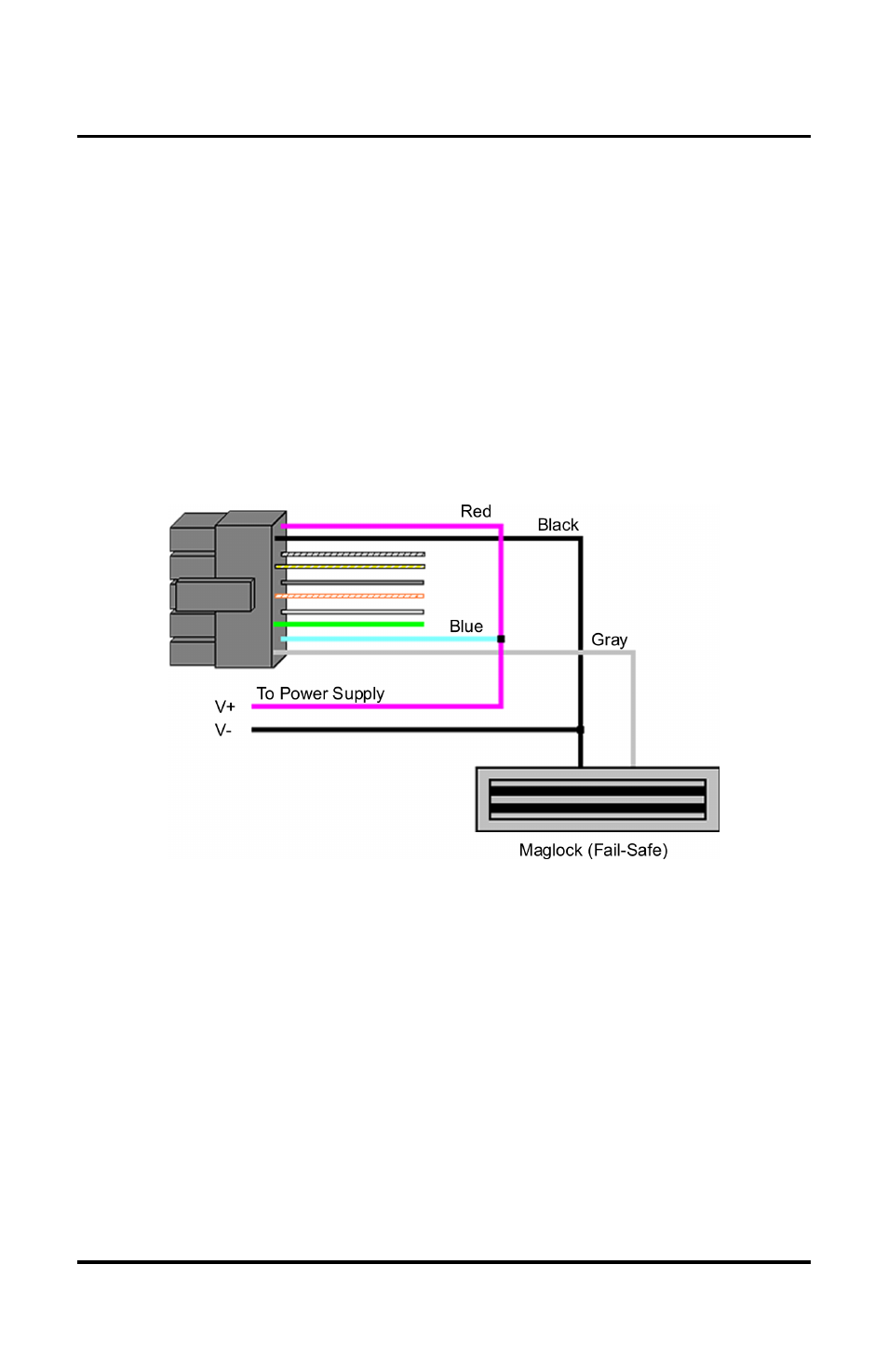
5.2 Wiring the Keypad to a Maglock (Fail-Safe)
Use the following steps to connect the keypad to a Maglock (Fail-
Safe):
1. Connect the red wire (V+) to the blue wire (common), and then
connect them to the positive on the power supply.
2. Connect the gray wire (normally closed) to the positive on the
Maglock.
3. Connect the black wire (V-) to the negative on the Maglock, and
then connect them to the negative on the power supply.
5.3 Wiring the Keypad to an Electric Strike (Fail-Secure)
Use the following steps to connect the keypad to an electric strike
(fail-secure) (see Figure 6 for reference):
1. Connect the red wire (V+) to the blue wire (common), and then
connect them to the positive on the power supply.
2. Connect the green wire (normally open) to the positive on the
strike.
3. Connect the black wire (V-) to the negative on the strike, and
then connect them to the negative on the power supply.
Figure 5 Wiring the Keypad to a Maglock (Fail-Safe)