1 virtual outputs – Controlled Products Systems Group 212ILW User Manual
Page 17
212iLW/242iLW Standalone Keypad
Installation/Programming Manual
Document # 6050700, Rev. 1.1, D2d
17
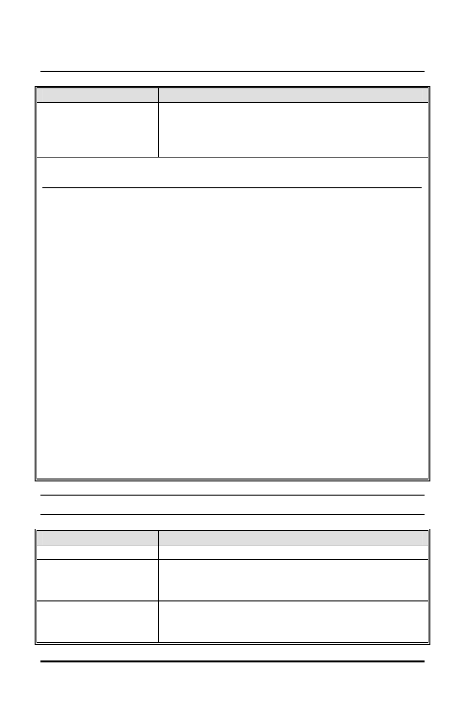
Command/Action
Keys to Enter/Details
Command 10
Assign Virtual
Outputs to Physical
Outputs
10 # virtual output # physical output # **
Virtual Output List
Physical Output List
0 – No Mapping
(Physical output unused)
1 – Relay 1 (Main Relay)
1 – Lock Output*
2 – Relay 2 (K2); (242 model)
2 – Alarm Shunt Output (242)
3 – Relay 3 (K3); (242 model)
3 – Propped Door Output**
4 – Relay 4 (K4); (242 model)
4 – Forced Door Output**
9 – Audio Alert #1
5 – OUT2 (242)
10 – Audio Alert #2
6 – OUT3 (242)
7 – OUT4 (242)
8 – OUT5 (242)
Note: Audio alerts are described
in section 7.2.2
13 – Duress Output (242)
14 – Panic Output (242)
15 – Keypad Active Output (242)
* The bi-color red/green LED only follows the lock output.
**On the 212 model, you can assign these to the audio alerts.
Defaults – The keypad comes
programmed with the following
default output assignments:
The Lock Output is assigned to
Relay 1, the Alarm Shunt Output
to Relay 2, the Propped Door
Output to Relay 3 and the Forced
Door Output to Relay 4.
7.2.1 Virtual Outputs
Virtual Outputs
Description/Details
Lock
This output is used for your locking device.
Alarm Shunt (242)
This is used to shunt out an existing alarm panel.
It activates with the lock output and de-energizes
one second after the lock time expires.
Propped Door
This output activates after entering a valid user
code only if the door position switch is left open
longer than the programmed propped door time.