Specifications – Controlled Products Systems Group 212ILW User Manual
Page 4
212iLW/242iLW Standalone Keypad
Installation/Programming Manual
Document # 6050700, Rev. 1.1, D2d
4
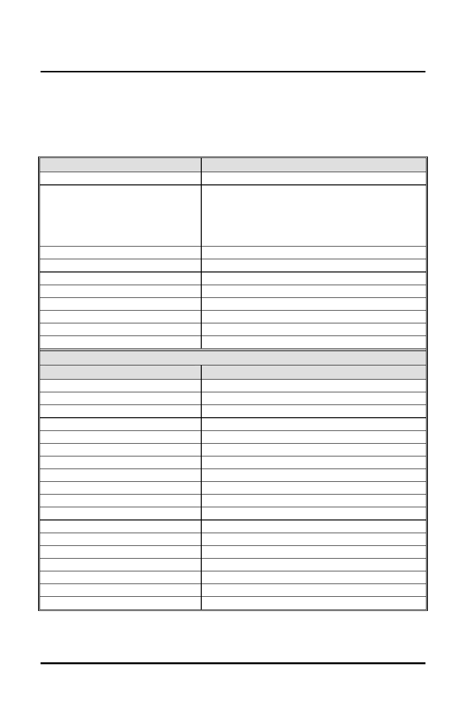
2. Specifications
Parameter
Range/Description
Voltage
10–30 VDC, 12-24VAC (Auto-Adjusting)
Current
93mA @ 10VDC; 158mA @ 30VDC,
148mA @ 12VAC; 198mA @ 24VAC
242 Model - Add 25mA for each energized
aux relay (max = 75mA)
Environment
For Indoor and Outdoor Use
Temperature Tolerance
-20° F to 130° F (-28° C to 54° C)
Dimensions
5 1/8" H x 3 3/8" W x 5/8" D
Main Relay (Form C)
Contact Rating: 2A @ 30VAC/DC
Aux Relay (Form C)
Contact Rating: 1A @ 24VAC/DC
REX Input
Normally Open Dry Contact
Door Position Input
Normally Closed Dry Contact
LEDs
Bi-Color Red/Green; Yellow
Default Keypad Settings
Parameter
Default Setting
Master Code
1234
Lock Output
Relay 1 (Main relay – 212 and 242)
Alarm Shunt Output
Relay 2 (242)
Propped Door Output
Relay 3 (242)
Forced Door Output
Relay 4 (242)
Audio Alerts
Not Assigned (212 and 242)
REX
Triggers Lock Output
REX Operation
Always Triggers (regardless of Door Loop)
Error Lockout
Enabled
Error Lockout Threshold
3 Attempts
Error Lockout Duration
10 Seconds
Lock Output Time
5 Seconds
Propped Door Output Time
30 Seconds
Forced Door Output Time
10 Seconds
Visual Keypress Feedback
Enabled
Audio Keypress Feedback
Enabled
Auto-Entry Disabled
User Lockout
Enabled