Wiring diagrams, Standard control box, Attach to outlet metal chassis with a single screw – Controlled Products Systems Group LA500 User Manual
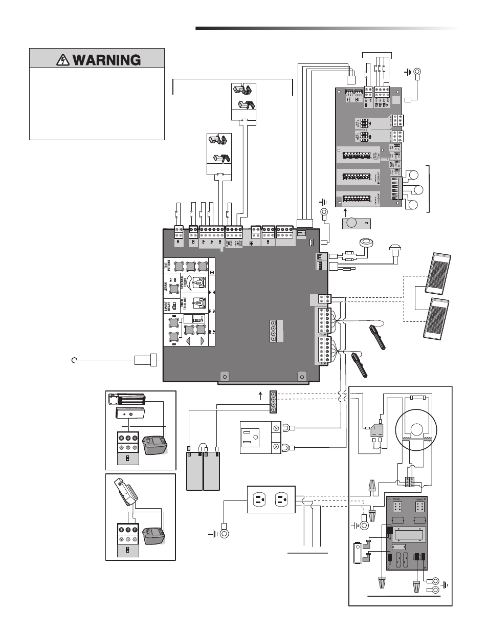
Page 44: Photoelectric sensors, Photoelectric sensors edge edge, Field wiring exp ansion board, Piezo alarm, Reset switch, Loop detector field wiring, Field wiring
42
To protect against fire and electrocution:
• DISCONNECT power and battery BEFORE
installing or servicing operator.
For continued protection against fire:
• Replace ONLY with fuse of same type and
rating.
STANDARD CONTROL BOX
WIRING DIAGRAMS
Attach to Outlet Metal Chassis With a Single Screw
SET
OPEN
SET
CLOSE
MO
VE
GA
TE
OFF
5
10
60
180
MIN
MAX
(SECONDS
OFF
ON
OPEN
CLOSE
STOP
NPUT PO
WER
BA
TT CHARG
NG
T
MER
GA
TE MO
V
NG
BA
TT LO
W
A
CC PWR O
VLD
D
A
GNOST
C
CODES
ST
A
TUS:
SBC
“F
RE
DEPT
”
OPEN
EX
T
SHADO
W
CLOSE
EYES/
NTERR
UPT
LOCK
NO
COM
NC
+
+
ACCESSOR
Y
POWER
ON SW
EXP
BOARD
XM
TTER
NE
TWORK
PRESS & RELEASE TO BEG
N
SE
TUP
CLA
S 2 SU
PL
Y
24 VO
TS
1
L
M
T
2
+
+
J5
+ -
SOLAR /
CHARGER
Photoelectric Sensors
Photoelectric Sensors
Edge
Edge
J15
Field Wiring
EXP
ANSION BOARD
Yellow
Blue
Black
Red
+ -
BA
TT
- + DC PO
WER
D RESET
ALARM
Piezo Alarm
White
Wh te
Purple
Reset Switch
Red
Black
GR
OUND
BR GRN
WT
YE BLU RED
BR GRN
WT
YE BLU RED
Loop Detector
Field Wiring
Wire Loop
Wire Loop
Wire Loop
Field Wiring
N.C.
Brown
Purple
Transformer 200 V
A
+ -
-
Bridge Rectifier
Wire Nut
Gray
Blue
12V 7AH Batter
y
Black
Red
12V 7AH Batter
y
To J15
Primar
y Operator
Secondar
y Operator
Black
Red
Yellow
White
Red
Orange
Two 12V Solar Panels in Series
+
-
-
+
Black
Red
N
GND
GND
L
N
Input Power Connection
Input Power Connection
EMI FIL
TER/SURGE PROTECTION BOARD
L
Switch/5A Breaker
Tranformer Run Kit (Optional)
Accessor
y Power Outlets
Attach to Metal Chassis
Black
Black
Red
White
Ground
Transformer
Black
Red
Connect Outlets to T
ransformer
Kit (If Used)
LOCK
NO
COM
NC
Maglock (Optional)
(not provided)
LOCK
NO
COM
NC
Solenoid Lock (Optional)
(not provided)
GR
OUND
Attach to Outlet Metal Chassis With a Single Screw
Antenna
(+)
(-)
(+)
(-)