Installation, Introduction, Description – Clear-Com VOICE2 User Manual
Page 41: Connecting the voice, Installation -1, Introduction -1, Description -1, Connecting the voice -1, Unit rear connectors -1
Vitec Group Communications
VoICE IP Interface User Manual
3 - 1
INSTALLATION
INTRODUCTION
This chapter describes the installation and setup of the IP Interface
product, including cable connections and configuration. The following
subjects are covered in this chapter:
• Description
• Installation in a rack
• Wiring
• Setup
DESCRIPTION
The VoICE unit is a 1U rackmount module that allows panels and
audio matrices to be connected over a standard network using Internet
Protocol (IP). The units are configured using an internet browser
running on a PC.
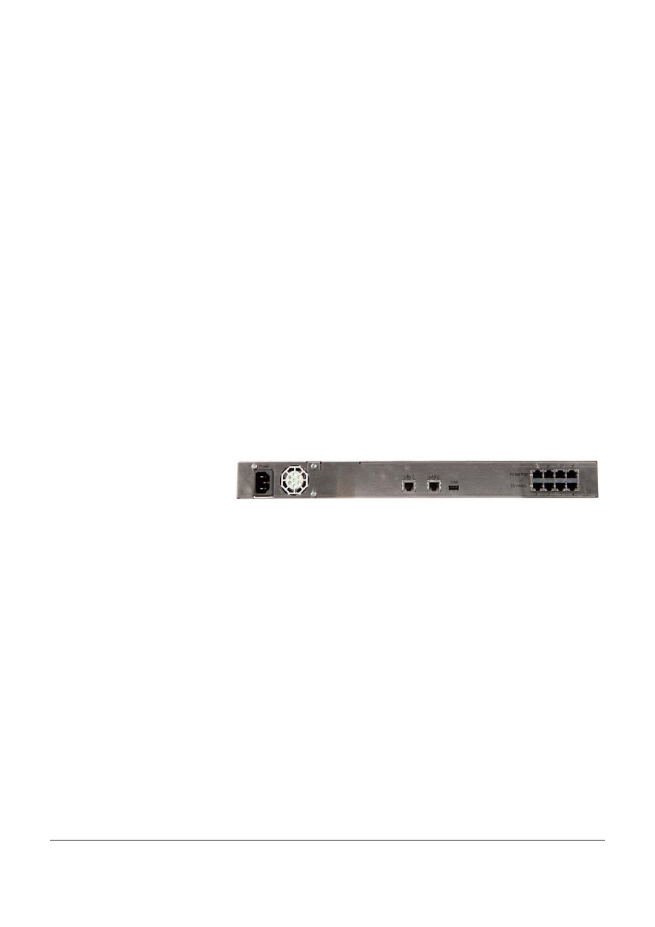
Figure 3-1: Unit Rear Connectors
CONNECTING THE VOICE
Here are the steps to connect and setup the product for the first time:
1. Make sure that all units are powered down (Power LEDs are off).
2. Connect one end of an Ethernet network cable to LAN1 port on the
back of the unit. Connect the other end to an Ethernet port on a
network device, e.g. a router or switch.
3. Connect one end of an Ethernet network cable to one of the
numbered ports on the back of the unit (to a “TO PANEL” port if you
connect to a panel and “TO MATRIX” port if you connect to an audio
matrix). Connect the other end to a panel “TO MATRIX” RJ-45 port
or to an audio matrix port.
4. Repeat this step to connect up to four ports to the audio matrix or to
different panels.
5. Connect the power cable. The Power LED on the unit front panel
will light up as soon as the power cable is connected properly.
3