Step 6 – Clear-Com V24PDXY User Manual
Page 8
V-Series AES-3 Option
Clear-Com Communication Systems
PN 810388Z Rev. 2
8
© Clear-Com Communication Systems
Step 6
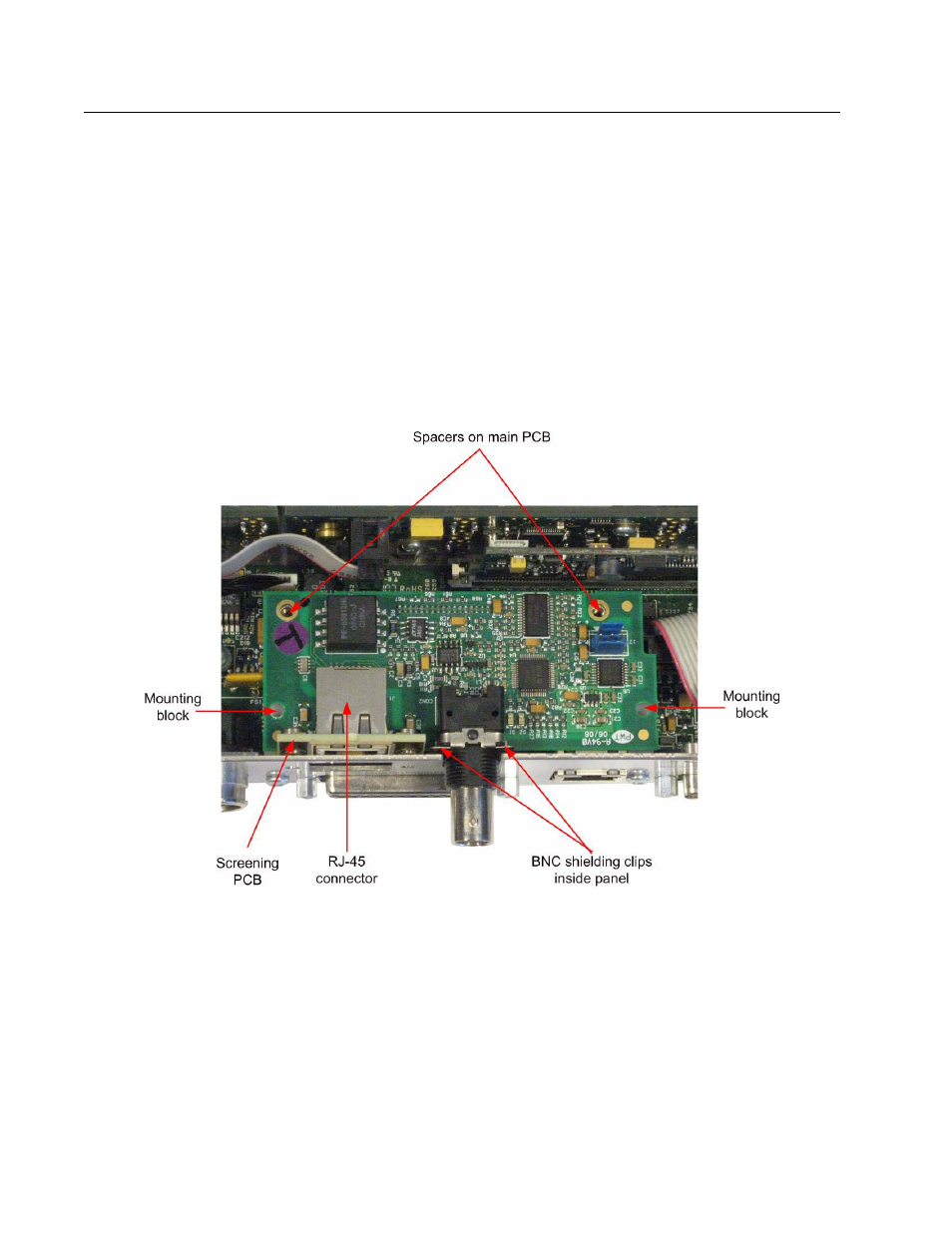
Slide the AES-3 option card vertically down onto the panel main PCB ensuring
that the BNC shielding clip is on the inside of the panel.
Care should be taken that the PCB connector pins on the AES-3 card are
aligned with the connector on the PCB to prevent any pins being bent when
the card is fitted. Do not use excessive force to fit the card as this may
damage the connector if the pins are misaligned.
Ensure that the mounting holes at the rear of the AES-3 card line up with the
spacers fitted to the V-Series panel main PCB . Press the top of the screening
PCB forward so that it is in contact with the back of the panel (Figure 11).
Figure 11: AES-3 Option card in V-Series Rack Mount Panel