Wiring a version with cable gland, English – Burkert Type 8011 User Manual
Page 29
29
Installationandwiring
Type 8011
6-36 V DC
+
-
(*)
1
2
3
4
5
blue
grey
white
brown
Load
Power supply
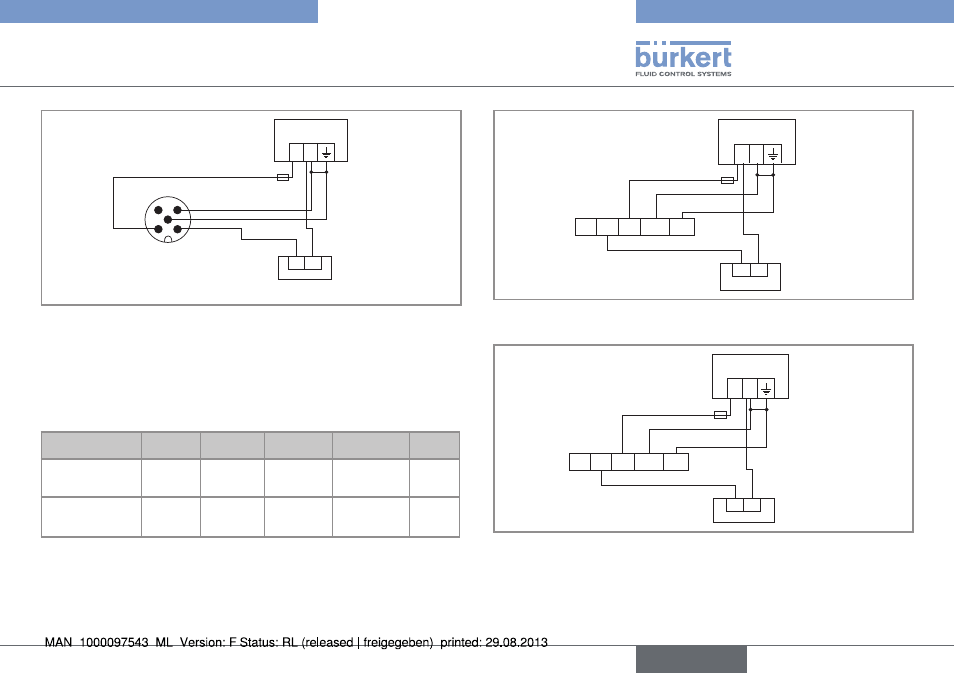
Fig. 11: PNP wiring of the pulse output of a version with M12 fixed
connector
(*) Functional earth; If a direct earth connection is not possible, fit a 100 nF /
50 V capacitor between the negative power supply terminal and the earth.
7.4.3. Wiring a version with cable gland
color of the wire
bn
(brown)
Wh (white) Gn (green) ye (yellow)
Gy
(grey)
Signal on a version
with 1 pulse output
V+
0 V DC
Functional
earth
Not connected NPN
Signal on a version
with 2 pulse
outputs
V+
0 V DC
Functional
earth
PNP
NPN
+
-
(*)
YE GY BN WH GN
Load
grey
brown
white
green
Power supply, 4,5-24 V DC or
6-36 V DC
Fig. 12: NPN wiring of the pulse output of a version with cable
gland
6-36 V DC
+
-
(*)
YE GY BN WH GN
Power supply
Load
brown
grey
white
green
Fig. 13: PNP wiring of the pulse output of a version with cable
gland
(*) Functional earth; If a direct earth connection is not possible, fit a 100 nF /
50 V capacitor between the negative power supply terminal and the earth.
English