Burkert Type 3003 User Manual
Page 14
14
Installation
→
Lift the cover off.
→
Wire the connections of the additional limit switches (FC1 and FC2)
according to the circuit diagram figures (see “Fig. 2”
and “Fig. 3” ).
→
Tighten the cable gland after connecting the terminals.
→
Set the cover in place and screw it tight.
→
Reinstall the position indicator.
Only use 4 or 6 conductor cable with a diameter of 7 ... 12
mm for the ISO20 cable fitting.
Ensure that the cable in the ISO20 cable fitting is com-
pletely sealed when tightening the union nut.
7.3.1. setting the limit switches
The rotary actuator is supplied with the following factory
settings:
• The CLOSED limit switches are activated with the cams 2
and 4 (closed position).
• The OPEN limit switches are preset at a 90° rotation
angle.
The procedure for setting the limit switches is shown in “Fig. 4”
.
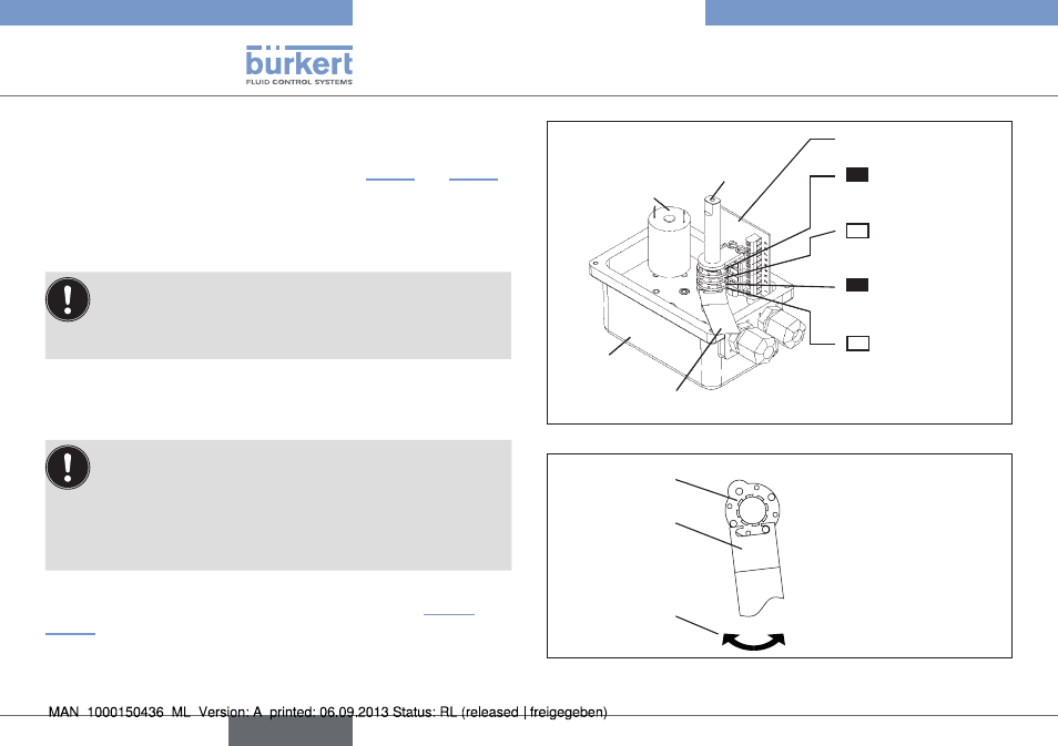
Electronic card
Shaft
Motor
Body
Wrench (00679946)
Cam No. 4
Additional limit
switch CLOSED
clOsed
black
Cam No. 3
Additional limit
switch OPEN
Open
white
Cam No. 2
Motor limit switch
CLOSED
clOsed
black
Cam No. 1
Motor limit switch
OPEN
Open
white
Fig. 4: Setting the limit switches. Limit switches max. 250 V / 5 A
Setting in
clockwise direction
or setting in
counter clockwise
direction
Cams
Wrench
Adjustment
direction
Fig. 5: Setting limit switches in counter clockwise and clockwise
directions
english
Type 3003