Burkert Type 8741 User Manual
Page 21
21
Installation
Type 8741
7.6.1 connect the power supply and
communication cable
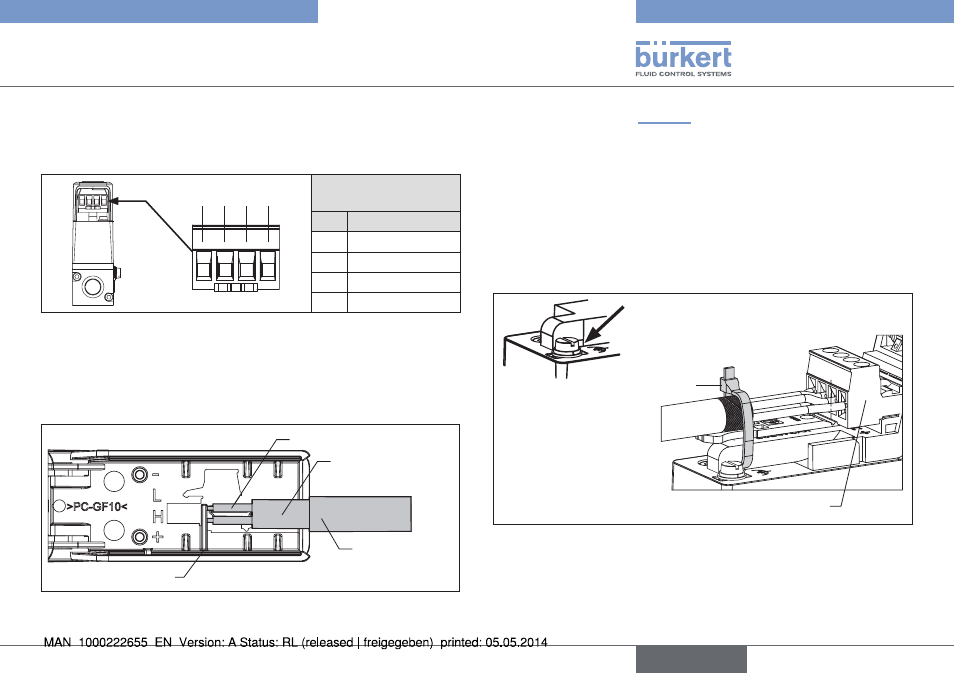
electrical input assignments:
1 2 3 4
screw terminals,
4-pin
Pin Assignment
1
DGND
2
CAN_L
3
CAN_H
4
24 V
Fig. 12 : Assignment; screw terminals, 4-pin
procedure:
→
Open the protective cover of the MFM/MFC.
On the inside of the protective cover there are engraved symbols
and a support as a stop for assembly of the cable.
Sheath
insulation
Braid
Cable shielding
Support
Fig. 13 : Assembly of the cable for the electrical connection
cable assembly: (See "Fig. 13")
→
Remove the insulation sheath over a length of approx. 25 mm.
→
Shorten the cable shielding to the required length (see engraved
symbols on the inside of the protective cover).
→
Pull back the cable shielding over the insulation sheath.
→
Attach the braid according to the assignment on the screw ter-
minals of the plug connector.
→
To relieve any strain on the cable, secure it to the housing of the
MFC/MFM using a cable tie.
Recess for attaching the
cable tie
Cable tie
Plug connector
Fig. 14 : Attached cable with strain relieved by cable ties
English