6 electrical data – Burkert Type 8741 User Manual
Page 15
15
Technicaldata
Type 8741
0
10
20
30
40
50
60
70
80
90
100
110
120
130
0
5 10 15 20 25 30 35 40 45 50 55 60 65 70 75 80
Q [l
N
/min]
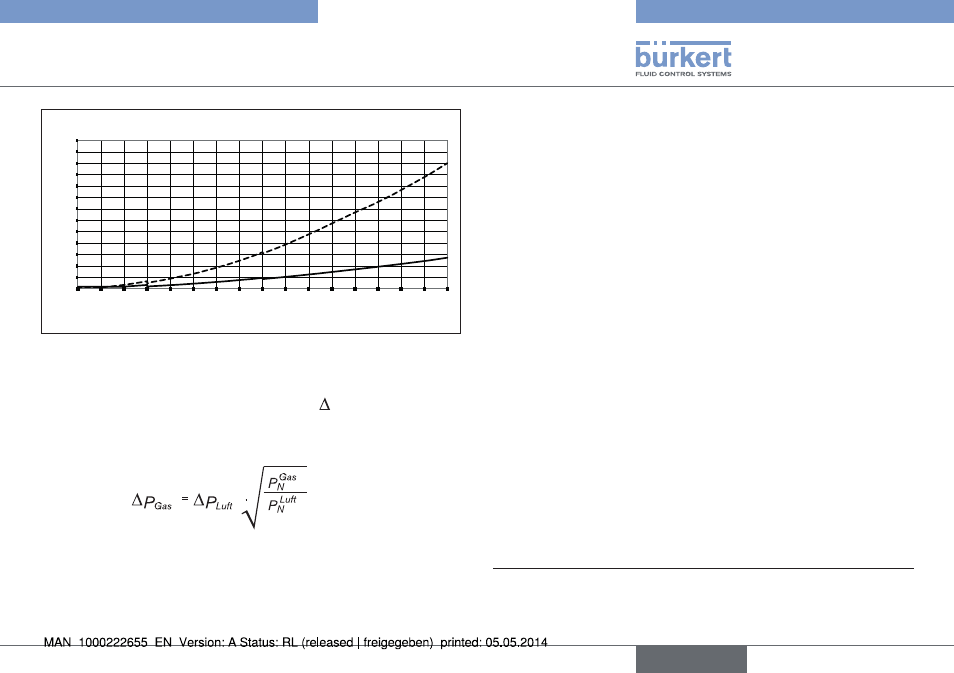
∆p [mbar]
Flange
1/4''
Fig. 3 : Pressure loss diagram, for air, with a 250 µm input filter,
for MFM type
For other operating gases, the pressure drop p
air
can be read from
the graph as a function of the flow rate Q
air
. For the same flow rate
of the operating gas Q
Gas
= Q
air
the pressure drop can be evaluated
using the
formula.
Under the root are the densities of the operating gases and of air
in the normal state according to DIN 1343 (P
N
= 1013.25 mbar,
T
N
= 273.15 K).
6.6
electrical data
Operating voltage
MFC:
24 V DC ± 10 %;
residual ripple < 2 %
MFM:
24 V DC ± 10 %
Max. Power consumption:
MFM :
< 1 W
MFC:
Dependent on the proportional
valve used, see nameplate
Communications interface:
büS or CANopen
LEDs:
1 LED
in accordance with Namur 107*
Electrical connections:
4-pin terminals,
5.08 mm grid
*
Standards committee for measurement and control technology (NAMUR)
is an international association of users of automation systems for the
process industry.
English