4 operation of the mfc (mass flow controller), Yx x – Burkert Type 8741 User Manual
Page 10
10
Systemdescription
Type 8741
5.4
operation of the mfc (mass
flow controller)
design:
• The mass flow is measured by a sensor.
• The MFC is fitted with electronics and a low-friction proportional
valve with a high response sensitivity to control the mass flow.
note!
malfunction due to contamination.
For problem-free functioning of the MFC, a filter must be installed
in front of the device for contaminated operating media.
See section "6.3.1 Quality of the operating medium"
operation:
The sensor measures the mass flow and relays the measured value to
the integrated electronics. The electronics compares the measured
current value (x) with the desired setpoint value (w) and calculates the
control value to be transmitted to the proportional valve (Y) in order
to control its opening.
The mass flow is either kept stable at a constant value or altered
according to a predefined profile.
The regulation is performed independent of pressure fluctuations or
increased flow resistance, such as might be caused by dirty filters.
The short response time of the proportional valve and the dynamics of
the sensor determine the setting time.
The measured mass flow value is transmitted to an external device via
a digital output (fieldbus).
In order to obtain a dynamic or quiet measured-value
output signal, the damping of this signal can be adjusted by
the "Bürkert Communicator" software. See section "12.3
Bürkert Communicator (PC software)"
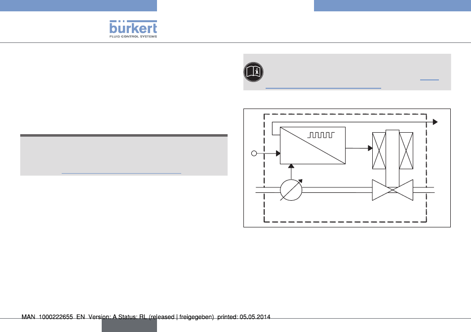
Function diagram:
w
x
out
y
x
x
d
= w-x
Electronic
Sensor
Proportional valve
Medium
inlet
Medium
outlet
Fig. 2 : Function diagram of the MFC (Mass Flow Controller)
English