Burkert Type 2080 User Manual
Page 5
english
16
8. insTallaTiOn
8.1. safety instructions
Warning!
Risk of injury from improper installation!
• Installation may be carried out by authorized technicians
only and with the appropriate tools!
Risk of injury from unintentional activation of the
system and an uncontrolled restart!
• Secure system from unintentional activation.
• Following installation, ensure a controlled restart.
8.2. fluid installation
Danger!
Danger – high pressure!
Serious risk of injury when reaching into the equipment.
• Before loosening the lines and valves, turn off the pres-
sure and vent the lines.
Check that the operating conditions correspond
with the performance data of the device.
english
17
Installation position:
Installation can be in any position.
→
Install upright for self-draining (body to bottom and in
the case of threaded port and welded ends install at a
min. gradient of 1° for drainage of media).
Installation
→
Before installation, clean any possible dirt off the pipelines
and flange connections.
→
If necessary, install a dirt trap in front of the valve to protect
it from malfunctions.
Mesh size:
0.1 ... 0.4 mm
Warning!
Danger - escaping medium!
Leaky connections with seals not properly seated.
• Fit all connections carefully and seal properly.
Seal the threaded port with a suitable sealing
material (PTFE tape is recommended).
english
18
Use the correct size of open-ended wrench to
screw in the pipelines; do not use the valve actuator
as a screwdriver!
The device must not be subject to any lateral
tension forces. The device connections must be in
alignment with the lines!
→
Attach the valve according to the connections:
Threaded port by screwing in the pipes,
Welded connection by welding,
Flange by screwing on.
Flange interface on the valve
16
16
Ш 4.5
Ш 3.1; 6 deep;
Option for positioning pin ø 3
(ensure correct location for installation)
16
16
13
english
19
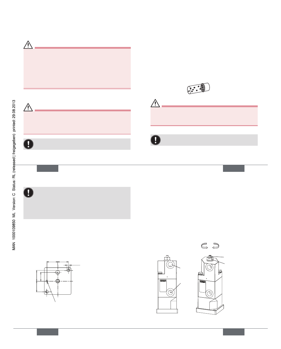
8.3. Option: Valve with 3 position
actuator (with adjustable
intermediate position)
Functions of the valve:
• Closed (without pilot air, by spring force),
• Partial stroke (pilot air simultaneously on X and Y),
• Full stroke (pilot air on X only).
Adjusting spindle
Lock nut
Stroke setting on the spindle
Flange version
Y
X
Flow
plus minus
Type 2080