Flomega, liquid mfc’s/mfm’s – Brooks Instrument 5882/92 User Manual
Page 18
18
Installation and Operation Manual
X-TMF-FM-MFC-eng
PN 541-C-007-AAG
April, 2008
Flomega, Liquid MFC’s/MFM’s
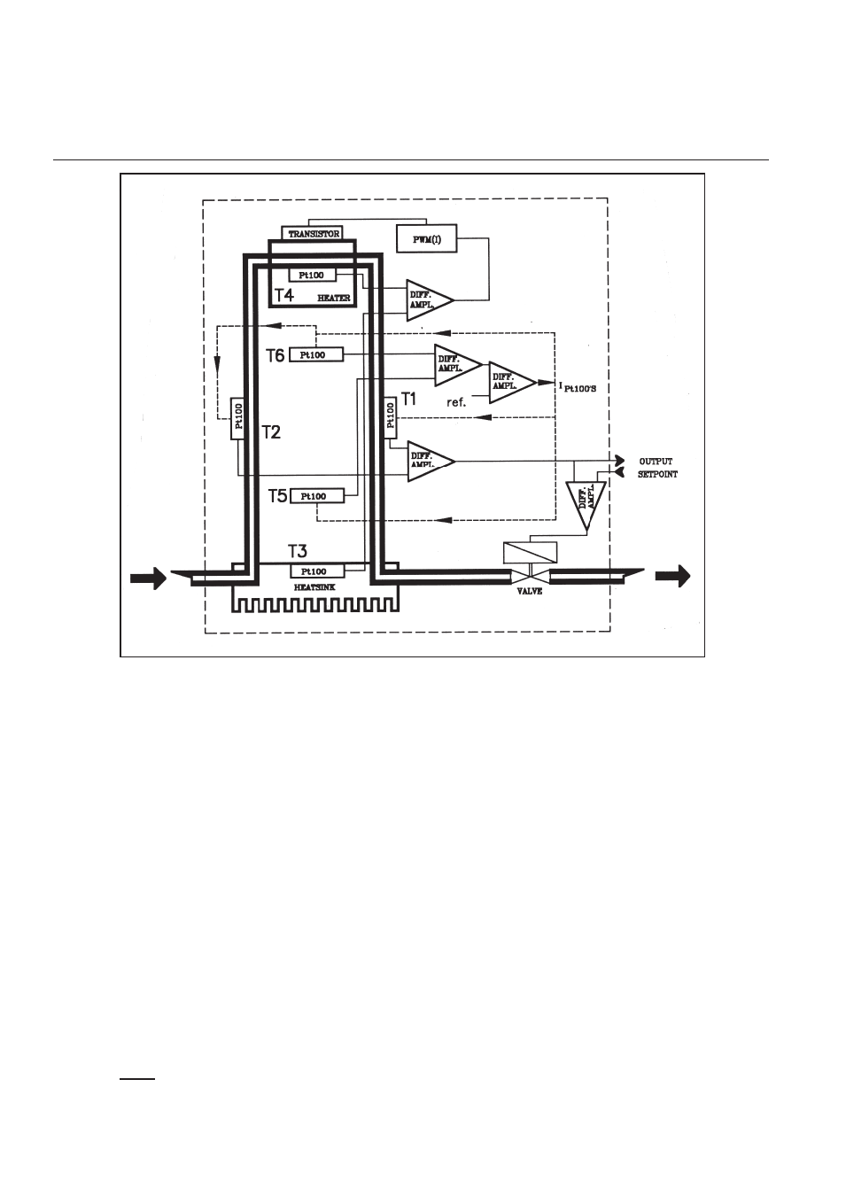
Figure 3-3 Principle Mass Flow Controller
MODEL 5881/91
ELECTRONIC FEATURES (see figure 3-4)
The Flomega model 5881 liquid mass flow controller and model 5891 liquid mass flow meter has a
number of features which are customer selectable (by jumper setting) or adjustable (by potentiometer).
These are:
a. Voltage or current setpoint
This is jumper selectable. For 0-5 Vdc setpoint insert jumpers J9, J10 and J11 to position “0”. For 0-20
mA setpoint insert jumper J9 to position “X” and jumpers J10 and J11 to position “0”. For 4-20 mA
setpoint insert jumper J9, J10 and J11 to position “X”.
b. 0-20 mA or 4-20 mA output
This is jumper selectable. For 0-20 mA output insert the jumpers J6 and J7 to position “X” and jumper
J8 to position “0”. For 4-20 mA output insert jumpers J6 and J7 to position “0” and jumper J8 to
position “X”. 0-5 Vdc output is always available. Voltage output: 6, 7, 8 “0”.
c. Proportional gain
By adjusting potentiometer P4, the proportional gain can be changed. This will enable you to optimize
your response.
d. Valve Over Ride
When applying +5 Vdc to +15 Vdc on pin number 12 of the connector, the valve is commanded to the
fully open position independent of the setpoint. When applying -15 Vdc to 0 Vdc on pin number 12 of
the connector, the valve is commanded to the closed position independent of the setpoint.
Note:
Excessive high flowrates, around
≥
200% full scale setting, may produce a decreasing output
signal.The output signal is limited up to 6.8 Vdc and 24 mA.
Section 3 Theory of Operation